Key takeaways
- An IEC 60617 motor symbol is a circle containing the letter M, with 3~ beneath it for a three-phase AC motor and a DC sign for a DC motor.
- Three-phase supplies are marked 3~ or 3Ø, and 3N~ 400/230 V 50 Hz denotes a three-phase four-wire system with neutral.
- A three-wire start-stop circuit places the NC stop button, NO start button with seal-in contact, and overload contact 95-96 in series with the contactor coil.
- NEC 430.6 requires conductor sizing from Table 430.250 full-load current, for example 27 A for a 20 hp 460 V motor, not from nameplate current.
- Overload relays are set from nameplate current under NEC 430.32, at up to 125% for motors with a 1.15 service factor or higher.
Quick answer: Motor control symbols represent the motor, its starter and its control logic. A motor is a circle with M, marked 3~ for three-phase AC, 1~ for single-phase or with a DC sign for DC. The starter appears as contactor contacts and overload elements in the power circuit, while the ladder diagram shows the coil, start and stop pushbuttons, seal-in and overload contacts.
Motor circuits are the most common control circuits in industry, and their drawings follow a consistent pattern: a power circuit from the supply through protection, contactor and overload to the motor, and a control circuit drawn as a ladder that decides when the contactor closes. Once you recognize the handful of motor electrical symbols involved, almost any starter drawing becomes readable.
This guide is for maintenance electricians, controls engineers, panel builders and students. It explains motor and three-phase symbols in IEEE and IEC practice, solenoid symbols, the standard power and ladder schematic diagram of a motor starter, reversing and reduced-voltage variations, and how to check motor current and overload settings from the drawing data.
What Does the Motor Symbol Look Like?
A motor symbol is the graphic representing a rotating electrical machine that converts electrical energy into mechanical work. Both IEC and IEEE build it on a circle, with letters and marks inside or beside it to show the machine type.
| Motor | IEC 60617 | IEEE 315 / North American practice |
|---|---|---|
| Three-phase AC motor | Circle with M, and 3~ below it | Circle with M or MOT, three leads T1, T2, T3 |
| Single-phase AC motor | Circle with M and 1~ | Circle with M, two leads; capacitor shown if capacitor-start |
| DC motor | Circle with M and a DC sign (line or ⎓) | Circle with M and two small rectangles at the sides for brushes |
| Generator | Circle with G and 3~ or DC sign | Circle with G or GEN |
| Three-phase motor showing windings | Circle with M 3~ and six terminals U1-V1-W1, U2-V2-W2 | Circle with leads T1-T6 (or T1-T9 for dual voltage) |
| Motor with thermistor | Motor symbol plus a thermistor (rectangle with diagonal and θ) | Motor symbol with PTC leads noted |
On a single line diagram the motor symbol for a 3 phase motor is simply a circle with M, with kW or hp written beside it. On a schematic, the three line conductors entering the circle show the phases, and the terminal markings tell you whether the motor is connected for star or delta, or for low or high voltage.
The DC motor symbol deserves care: on some North American drawings a circle with A inside represents the armature, with the field winding drawn as a separate coil, which lets the schematic show shunt, series or compound connection. The three-phase electric motor guide explains the winding arrangements those terminals represent, and the general electrical symbols chart covers related source and converter symbols.
Three Phase Symbol and Power Supply Markings
The 3 phase symbol appears on nameplates, schedules and schematics in several forms:
- 3~: IEC marking for three-phase alternating current, used beneath motor symbols and on nameplates.
- 3Ø or 3PH: North American abbreviation for three phase, common on drawings and panel schedules.
- 3N~: three-phase with neutral, for example
3N~ 400/230 V 50 Hzfor a four-wire system. - 3/N/PE: conductors listed explicitly, three phases, neutral and protective earth, as on IEC distribution drawings.
- Δ and Y: delta and wye (star) connection symbols, drawn as a small triangle or Y beside a transformer or motor winding.
The electrical 3 phase symbol on a power drawing is often supplemented by phase identification: L1, L2, L3 in IEC practice, A, B, C or L1, L2, L3 in North America, and conductor colors per local rules. Our three-phase color code guide lists those conventions.
| Marking | Meaning |
|---|---|
| 1~ 230 V 50 Hz | Single-phase AC |
| 3~ 400 V 50 Hz | Three-phase three-wire |
| 3N~ 400/230 V 50 Hz | Three-phase four-wire with neutral |
| 3Ø 480 V 60 Hz | Three-phase, North American style |
| 480Y/277 V | Wye-connected source, 480 V line to line, 277 V line to neutral |
A three phase power symbol on a single-line diagram is not usually drawn at all, since one line represents all three phases; instead the voltage and number of wires are written on the bus label.
Solenoid Electrical Symbol and Related Actuators
A solenoid is an electromagnetic coil that moves a plunger in a straight line when energized, used to operate valves, brakes, locks and breaker trip mechanisms. The solenoid electrical symbol varies with drawing type:
- NEMA / JIC ladder: a coil drawn as a series of loops or humps, labeled SOL with a number, such as SOL-1. Some drawings use a circle labeled SOL like a relay coil.
- IEC 60617: a rectangle (the general symbol for an operating coil), sometimes with a diagonal line through it, tagged by device type, often -YV for a solenoid valve under older IEC conventions or -MB under IEC 81346-2.
- Hydraulic and pneumatic drawings: per ISO 1219, the solenoid is a small rectangle with a diagonal line attached to the end of the valve symbol, the valve being a set of squares with flow arrows.
- Breaker shunt trip and closing coils: drawn like relay coils, tagged TC (trip coil) and CC (close coil) on North American drawings.
On a solenoid wiring diagram, the coil voltage and power are critical data: a 24 V DC solenoid valve drawing perhaps 8 W draws about 0.33 A, while AC solenoids have a high inrush current until the plunger seats. Those values decide whether a PLC output can drive the solenoid directly or needs an interposing relay, a check worked through in the switch and relay symbols guide.
Brakes on hoist and conveyor motors are usually shown as a solenoid or brake coil symbol next to the motor, wired so the brake releases only when the motor contactor is closed.
Motor Control Wiring Schematics: Power Circuit and Ladder
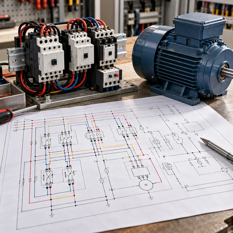
A motor starter schematic is drawn in two parts. The power circuit carries motor current; the control circuit, drawn as a ladder, operates the contactor coil.
Power circuit symbols, from supply to motor
- Disconnect switch or switch-disconnector, three blades linked by a dashed line.
- Short-circuit protection: fuses (rectangle with line) or an instantaneous-trip breaker or motor-protective circuit breaker.
- Contactor main contacts M, three NO contacts linked to the coil tag.
- Overload relay elements OL, one thermal or electronic element per phase.
- Motor, circle with M 3~, terminals T1, T2, T3.
Three-wire start-stop ladder
Between the control supply rails (often 120 V from a control transformer, or 24 V DC), a single rung contains, in series: the NC stop pushbutton, the NO start pushbutton, the contactor coil M and the NC overload contact (95-96). An NO auxiliary contact of M is wired in parallel with the start button as a seal-in (holding) contact. Pressing start energizes M, the seal-in contact closes and holds the coil after the button is released; pressing stop or an overload trip breaks the rung.
Pilot lamps on further rungs, a red lamp through an M auxiliary NO contact for running, and a green lamp through an NC contact for stopped, complete the basic circuit. Rung numbers down the left side and cross-references to the right of each coil tell you where that coil's contacts are used. Fuse and overload symbols are detailed in the circuit breaker and fuse symbols guide; control supply sizing is covered in the 24 V control transformer guide.
Reversing, Star-Delta and VFD Motor Schematics
Variations on the basic starter add symbols but follow the same structure.
| Starter type | Additional power circuit symbols | Additional control logic |
|---|---|---|
| Reversing (F/R) | Two contactors, F and R, with two line conductors swapped on the R contactor | NC contact of F in R coil rung and vice versa (electrical interlock); dashed line between coils for mechanical interlock |
| Star-delta | Main, star and delta contactors; motor drawn with six terminals U1-W2 | Timer coil with timed contacts transferring from star to delta; star and delta interlocked |
| Soft starter | Rectangle with thyristor qualifier, often with bypass contactor | Start/stop and fault contacts to the soft starter terminals |
| Variable frequency drive | Rectangle with ~ / ~ or with rectifier and inverter symbols inside | Run, speed reference (4-20 mA or 0-10 V), fault and ready signals |
| Two-speed | Separate contactors for low and high speed windings | Interlocks and compelling relays to prevent direct high-speed start |
A schematic diagram of motor reversing control always shows the interlocks, because energizing both contactors at once is a phase-to-phase short circuit. When reviewing drawings, trace that the NC interlock contacts are present and correctly cross-referenced.
The star-delta starter guide explains the transition timing, and the motor starter types guide compares DOL, reduced-voltage and drive starting. Terminal connections for six-lead and nine-lead motors are drawn in our three-phase motor wiring diagrams.
Worked Example: Motor Current and Overload Setting From the Drawing
Motor schedules and schematics give the data needed to verify conductors and overloads. Consider a 20 hp (14.9 kW), 460 V, three-phase motor with nameplate FLA 25 A, service factor 1.15, efficiency 90% and power factor 0.85.
Calculated current
I = P / (√3 × V × η × PF) = 14,920 / (1.732 × 460 × 0.90 × 0.85) ≈ 14,920 / 609.5 ≈ 24.5 A
That agrees closely with the 25 A nameplate value.
Conductor sizing
NEC 430.6(A)(1) requires conductor and short-circuit protection sizing from the table full-load current, not the nameplate. NEC Table 430.250 lists 27 A for a 20 hp motor at 460 V. Branch-circuit conductors must be rated at least 125% of that:
1.25 × 27 A = 33.75 A, so conductors rated at least 34 A at the applicable terminal temperature.
Overload setting
NEC 430.32(A)(1) bases overload protection on nameplate current. With a service factor of 1.15 or more, the maximum is 125%:
1.25 × 25 A = 31.25 A
An adjustable overload relay would be set at or below 31 A. In IEC practice, the overload is set at the motor rated current and the trip class (10, 20, 30) chosen per IEC 60947-4-1 to suit the starting time. These ratings should appear beside the overload symbol on the schematic.
Next Steps: Specifying Motor Control and Switchgear
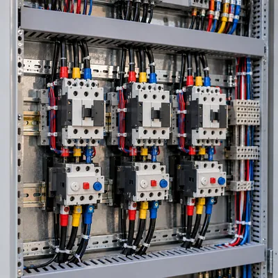
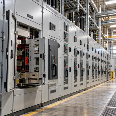
Motor control symbols eventually become equipment in a motor control center, LV switchboard or control panel. When preparing a specification:
- Produce a motor list with kW or hp, voltage, FLA, starting method, duty and location.
- Define starter type per motor (DOL, reversing, star-delta, soft starter, VFD), coordination type (Type 1 or Type 2 per IEC 60947-4-1) and overload trip class.
- Specify control voltage, interface signals to the PLC or DCS, and standard ladder or IEC schematic templates.
- State the switchboard or MCC form of separation, withdrawable or fixed units, and short-circuit rating.
MARS does not sell stand-alone motor starters or motors. We manufacture IEC 61439 LV switchboards, including GCS and MNS withdrawable designs widely used for motor feeders, as well as MV switchgear and the transformers that supply motor loads. See the HV and LV switchgear range and the motor control center guide, then send your motor list via the quote request form.
Frequently asked questions
What is the symbol for a 3 phase motor?
In IEC 60617 a three-phase motor is a circle containing the letter M with 3~ written below it, and three line conductors connected to it. North American drawings show a circle with M or MOT and terminals T1, T2 and T3. On single line diagrams the motor is a circle with M and its rating written beside it.
What is the three phase symbol on a nameplate?
Nameplates mark three-phase AC as 3~ under IEC practice, often with voltage and frequency, such as 3~ 400 V 50 Hz. North American nameplates and drawings often use 3Ø or 3PH. A marking of 3N~ indicates three-phase with neutral, for example 3N~ 400/230 V for a four-wire supply.
What does the solenoid symbol look like?
In NEMA ladder diagrams a solenoid is drawn as a coil of loops or humps labeled SOL with a number. IEC drawings use a rectangle, the general operating coil symbol, tagged as a solenoid valve or actuator. Hydraulic and pneumatic drawings per ISO 1219 show a small rectangle with a diagonal line attached to the valve symbol.
What is the symbol of a DC motor?
An IEC DC motor symbol is a circle with M and a DC sign, a straight line or solid line over dashed line. IEEE practice often draws a circle with M and two small rectangles representing brushes, or a circle with A for the armature and a separate field coil, which shows whether it is shunt, series or compound wound.
How do you read a motor control wiring schematic?
Start with the power circuit: follow the supply through the disconnect, fuses or breaker, contactor contacts and overload elements to the motor. Then read the ladder rung by rung from left to right: stop button, start button with its seal-in contact, coil and overload contact. Use rung cross-references to find each coil's contacts.
What is a seal-in contact in a motor circuit?
A seal-in or holding contact is a normally open auxiliary contact of the motor contactor wired in parallel with the start pushbutton. When the coil energizes, the contact closes and keeps the coil energized after the start button is released. Pressing stop or an overload trip opens the rung and the contactor drops out.
Written and reviewed by the MARS application engineering team in Shanghai, who specify and test transformers, switchgear, substations and battery storage for projects in 40+ countries. Last updated .
Tags: motor control symbols motor symbol 3 phase symbol solenoid electrical symbol three phase motor symbol