Key takeaways
- Most HVAC 24V transformers are Class 2 power sources limited to 100 VA at 30 V or less, with 40 VA and 75 VA the most common ratings.
- Secondary current is I = VA / 24, so a 40 VA unit delivers about 1.67 A and a 75 VA unit about 3.1 A.
- Using the 240 V tap on a 208 V supply gives only about 20.8 V output, which can make contactors chatter and drop out.
- Size control transformers for coil inrush, often 5 to 10 times sealed VA, not just the steady-state load, to keep voltage above about 85% during pickup.
- UL 5085-3 covers Class 2 transformers and IEC 61558-2-2 covers industrial control transformers; both influence fusing and marking requirements.
Quick answer: A 24V transformer steps 120 V, 208 V, 240 V or 277 V down to 24 V AC for thermostats, contactor coils, gas valves and control circuits. Choose the primary tap that matches the measured supply, size the VA rating above the sum of sealed loads plus coil inrush, and keep HVAC units within the 100 VA Class 2 limit.
Almost every furnace, air handler, rooftop unit, irrigation controller and industrial control panel depends on a small transformer producing 24 V AC. It is a modest component, but a wrong tap, an undersized VA rating or a reversed common wire is behind a large share of control-circuit faults: chattering contactors, blown 3 A fuses and thermostats that reset.
This guide is for HVAC technicians, panel builders and facility engineers who need to select or replace a 240v to 24v transformer, a 208 to 24v transformer or a 120 V version. It explains how multi-tap primaries work, gives text-based wiring diagrams for 120 V and 208/240 V supplies, shows how to size VA with inrush and covers Class 2 and fusing rules.
What Is a 24V Control Transformer?
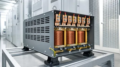
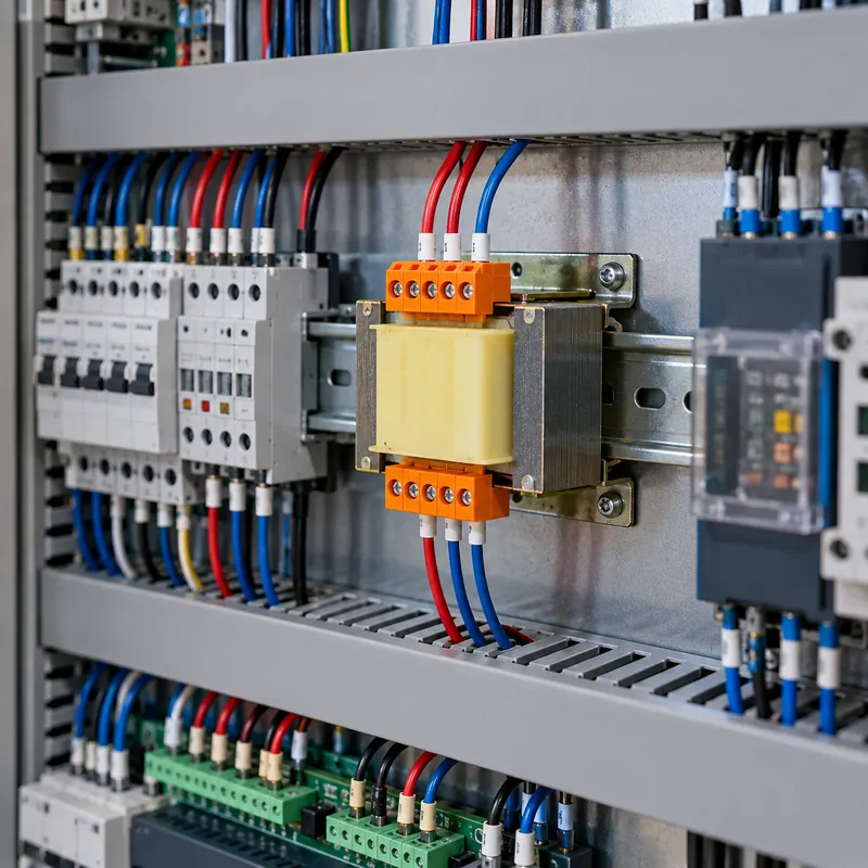
A 24V control transformer is a small step-down transformer that converts line voltage to 24 V AC to power control devices rather than the main load. Separating control power from line power keeps thermostat wiring at a touch-safe voltage, allows thin low-voltage cable and limits fault energy in the control circuit.
There are two families:
- Class 2 transformers (UL 5085-3), used in HVAC and building controls. Output is inherently or fuse-limited so the circuit qualifies as Class 2 under NEC Article 725, allowing low-voltage wiring methods. At 24 V nominal the limit is 100 VA.
- Industrial control transformers (IEC 61558-2-2, or UL 5085 general series), usually 50 VA to several kVA, with 24 V, 120 V or 230 V secondaries for machine control panels. These are sized for contactor inrush and are protected by fuses rather than inherent limiting.
The turns ratio defines the output. For a 240 volt to 24 volt transformer, N1 / N2 = 240 / 24 = 10. Small transformers also have significant regulation, so output at no load may be 26–28 V and fall to 24 V at rated VA. For the theory behind ratio and regulation, see our transformer turns ratio formula article and the broader small transformer engineering guide.
Multi-Tap Primaries: 120, 208, 240 and 277 V
Most replacement HVAC transformers have a multi-tap primary: one common lead plus separate leads for each supply voltage. A typical 208 240 to 24v transformer has a common, a 208 V lead and a 240 V lead, and universal units add 120 V and 277 V. Lead colors vary by manufacturer, so always read the label rather than relying on color.
The output depends on matching the tap to the actual supply. Because output scales with the ratio, using the wrong tap shifts the 24 V by the same percentage.
| Actual supply | Tap used | Output (nominal) | Result |
|---|---|---|---|
| 240 V | 240 V | 24.0 V | Correct |
| 208 V | 208 V | 24.0 V | Correct |
| 208 V | 240 V | 20.8 V | Low; contactors may chatter |
| 240 V | 208 V | 27.7 V | High; coils and valves run hot |
| 120 V | 240 V | 12.0 V | Controls will not operate |
| 277 V | 240 V | 27.7 V | High; avoid |
Measure the supply with the unit running before choosing the tap. A nominal 208 V supply that measures 216 V can still use the 208 V tap; a 230 V supply generally uses the 240 V tap. Our 208 vs 240 volts article explains why commercial buildings fed from 208Y/120 V often catch technicians out.
Insulate and cap the unused tap lead. It is live whenever the primary is energized, even with no load attached.
120V to 24V Transformer Wiring Diagram
The 120 to 24 volt transformer wiring diagram is the simplest case, used on furnaces, boilers and most residential air handlers. Described in text, the connections are:
- Primary: 120 V hot (black) to the 120 V tap lead; neutral (white) to the common lead; equipment ground to the transformer mounting plate or chassis.
- Secondary: one 24 V terminal becomes R (hot), the other becomes C (common).
- Thermostat: R to thermostat R; C to thermostat C if the thermostat needs continuous power; W, Y and G return from the thermostat to the heat relay or gas valve, the compressor contactor coil and the fan relay respectively. The other side of each coil returns to C.
In many furnaces the C side is bonded to chassis ground. That is acceptable for Class 2 circuits, and some ignition modules require it for flame sensing, but only one side may be grounded. If a replacement transformer has a grounded secondary lead, confirm it matches the side used as C.
A fuse, typically 3 A or 5 A, often sits in the R lead on the control board. If the fuse blows the instant the thermostat calls, look for a shorted coil or a pinched thermostat cable before replacing the transformer.
Work on equipment connected to the building supply must follow local code and, for line-voltage connections, be performed by a licensed electrician or qualified HVAC technician with the circuit locked out. For general low-voltage wiring practice see our guide to connecting low-voltage wires to a transformer.
240V and 208V to 24V Transformer Wiring Diagram
Rooftop units, condensing units and heat pumps usually have a 208/240 V single-phase or three-phase supply and no neutral in the unit. The 240v 24v transformer wiring diagram therefore connects the primary phase-to-phase.
- Lock out the unit disconnect and verify zero voltage at the line terminals.
- Measure or confirm the nominal supply (208 V or 240 V) from the nameplate and panel.
- Connect the transformer common lead to L1 (or the load side of the control fuse) and the matching 208 V or 240 V tap lead to L2. On three-phase units the transformer takes any two phases, usually L1 and L2.
- Cap the unused tap with an insulated connector rated for line voltage.
- Connect the 24 V secondary: R to the control board or thermostat R terminal, C to common.
- Bond the transformer mounting to the unit chassis and confirm that only one secondary lead, if any, is grounded.
- Restore power and measure 24–28 V across R and C before calling for cooling or heating.
Some equipment has a control-circuit fuse or breaker on the primary. Size it per the unit manufacturer's diagram or, for a field-installed transformer, per the transformer listing and the applicable NEC rules (Article 725 for Class 2 sources, 450.3 for transformers). A 208 to 24 volt transformer drawing 40 VA takes only about 40 / 208 = 0.19 A at full load, but its magnetizing inrush at switch-on is far higher, so time-delay fuses are preferred. The transformer wiring diagram guide shows the general H and X terminal conventions behind these connections.
How to Size a 24V Transformer in VA
VA (volt-amperes) is the rating that matters for a control transformer, because coil loads are inductive and their power factor is low. Size in three steps.
1. Add the sealed VA
Sealed VA is what each coil draws when held in. Use datasheet values or measure current: VA = 24 × I.
2. Check inrush
A contactor coil draws several times its sealed VA for one or two cycles as it pulls in. If the transformer is too small, voltage collapses during pickup and the contactor chatters. Industrial practice sums the inrush VA of devices that can energize together plus sealed VA of those already on, then selects from the manufacturer's regulation chart at about 40% power factor so secondary voltage stays at or above 85% of nominal.
3. Add margin and respect Class 2 limits
Allow 25–50% margin for added accessories such as zoning boards, humidifiers or smart thermostats. Above 100 VA, either split the load across two Class 2 transformers (with separate circuits that are not interconnected) or move to a non-Class 2 control transformer with Class 1 wiring methods.
| VA rating | Secondary current at 24 V (A) | Typical use |
|---|---|---|
| 20 | 0.83 | Thermostat-only, small zone valves |
| 40 | 1.67 | Furnace or air handler with one contactor |
| 50 | 2.08 | Heat pump with defrost board |
| 75 | 3.13 | Rooftop units, zoning systems |
| 100 | 4.17 | Maximum Class 2 at 24 V |
Worked Example: Heat Pump Air Handler Control Load
An air handler with a 208/240 V supply serves a heat pump. Its control loads are:
- Smart thermostat: 3 VA
- Compressor contactor coil: 7 VA sealed, 45 VA inrush
- Blower relay: 4 VA sealed, 20 VA inrush
- Reversing valve solenoid: 9 VA
- Electric heat sequencer: 6 VA
- Defrost and control board: 5 VA
Sealed total: 3 + 7 + 4 + 9 + 6 + 5 = 34 VA.
Worst-case pickup: the contactor and blower relay can energize together while the other loads are already on: 45 + 20 + 3 + 9 + 6 + 5 = 88 VA momentarily.
A 40 VA transformer runs at 85% of rating on the sealed load and would sag hard during that 88 VA pickup. A 75 VA Class 2 unit runs at 45% sealed and handles the momentary demand without dropping below about 20 V, because small transformers tolerate short overloads well beyond their continuous rating. Select 75 VA.
Secondary current: 75 / 24 = 3.1 A rated; normal running current is 34 / 24 = 1.4 A, so the 3 A board fuse is appropriate.
Primary current on the 208 V tap: 75 / 208 = 0.36 A at full rating. If the site actually measures 240 V, move to the 240 V tap; using the 208 V tap would give about 27.7 V and shorten coil life.
Troubleshooting Common 24V Transformer Faults
Most failures are caused by something downstream. Use this sequence before replacing the transformer.
| Symptom | Likely cause | Check |
|---|---|---|
| No 24 V output | Open primary fuse, failed winding, wrong tap | Measure primary voltage, then secondary open-circuit voltage |
| Board fuse blows on call | Shorted coil or thermostat cable | Disconnect loads one at a time and measure coil resistance |
| Contactor chatters | Low voltage from wrong tap or undersized VA | Measure R–C during pickup; should stay above about 20 V |
| Transformer hot or humming | Overload or high primary voltage | Measure secondary current against VA / 24 |
| Thermostat resets | Voltage sag when loads energize | Upsize VA or separate loads onto a second transformer |
A healthy small transformer typically shows a few ohms to tens of ohms on the primary and under 2 Ω on the 24 V secondary, though values vary widely by size. An open winding reads infinite. If you are testing larger equipment windings, our how to test a transformer guide covers ratio and insulation checks in more depth.
Next Steps: Specifying and Sourcing
For replacement HVAC transformers, specify primary taps, VA, Class 2 listing, mounting style (foot, plate or single-hub) and whether the secondary has a built-in breaker. For industrial panels, specify primary and secondary voltages, VA with inrush data, primary and secondary fusing, and compliance with UL 5085 or IEC 61558-2-2.
MARS does not sell stand-alone HVAC or panel-mount control transformers. Our focus is the distribution equipment upstream: dry-type distribution transformers that create the 208Y/120 V, 240 V or 400/230 V systems feeding these controls, plus LV switchboards and compact substations whose control and auxiliary supplies are specified as part of the assembly. If you are planning a new building service or a plant expansion, our 277 to 120 transformer guide covers a related small-load case, and our engineers can review a full single-line diagram. Send your requirement through the quote request form.
Frequently asked questions
How do I wire a 240V to 24V transformer?
With power locked out, connect the transformer common lead to L1 and the 240 V tap lead to L2, cap any unused taps, then connect the 24 V secondary to the R and C terminals of the control board or thermostat. Measure 24–28 V across R and C before operating the equipment.
Can I use a 240V to 24V transformer on 208V?
Only if it has a 208 V tap. A single-voltage 240 V primary on a 208 V supply produces about 20.8 V, which can cause contactor chatter and thermostat resets. Multi-tap 208/240 V units solve this by letting you select the tap that matches the measured supply.
What VA transformer do I need for a thermostat?
A thermostat alone draws 1 to 5 VA, but the transformer also powers the gas valve, contactor and relays. Most furnaces use 40 VA, and heat pumps or zoned systems commonly need 50 to 75 VA. Add sealed VA of all loads, allow for inrush and keep the total under 100 VA for Class 2.
Which wire is common on a 24V transformer?
The 24 V secondary has two leads, and either can be designated common (C) unless the transformer marks one as grounded. Once chosen, C must return to the common of every coil and the thermostat C terminal. If the equipment grounds C to chassis, use that same lead as common.
Why does my 24V transformer keep burning out?
Repeated failures usually point to a shorted coil, a pinched thermostat cable, a missing board fuse or the wrong primary tap applying high voltage. Check each load's coil resistance, inspect low-voltage cabling for damage and confirm the tap matches the measured supply before installing another transformer.
What is the difference between a 24V transformer and a 24V power supply?
A 24V transformer outputs 24 V AC and is used for AC coils, valves and thermostats. A 24V power supply is an electronic converter that outputs regulated 24 V DC for PLCs, sensors and DC relays. They are not interchangeable; a DC coil on AC or an AC coil on DC will malfunction.
Written and reviewed by the MARS application engineering team in Shanghai, who specify and test transformers, switchgear, substations and battery storage for projects in 40+ countries. Last updated .
Tags: 24v transformer 240v to 24v transformer 120v 24v transformer wiring diagram 208 to 24v transformer 24v transformer wiring diagram