Key takeaways
- A 277 to 120 transformer has a turns ratio of about 2.31:1, so a 10 kVA unit draws 36 A at 277 V and delivers 83 A at 120 V.
- It connects line-to-neutral on a 480Y/277 V system, so several units should be spread across phases A, B and C to keep the 480 V system balanced.
- NEC 450.3(B) allows primary-only protection at 125% of rated primary current for currents of 9 A or more, rounded up to the next standard size.
- The 120 V secondary is a separately derived system requiring a system bonding jumper and grounding electrode conductor per NEC 250.30.
- Many LED drivers and ballasts are rated 120–277 V, so check nameplates before adding a transformer for lighting loads at all.
Quick answer: A 277 to 120 transformer is a single-phase step-down transformer connected phase-to-neutral on a 480Y/277 V system to produce 120 V (or 120/240 V) for receptacles, controls and small equipment. Size it from the 120 V load with kVA = V × I / 1000, protect it per NEC 450.3(B) and ground the secondary as a separately derived system.
Commercial buildings in North America are commonly served at 480Y/277 V. Motors and HVAC run at 480 V three-phase, lighting runs at 277 V phase-to-neutral, and everything that plugs into a wall needs 120 V. Most of that 120 V comes from three-phase 480–208Y/120 V transformers, but there are many cases where a single-phase 277 to 120 transformer is the simpler and cheaper answer.
This guide is written for electrical designers, facility engineers and contractors choosing a 120 V transformer for signage, controls, a remote receptacle group or a retrofit where only a 277 V lighting circuit is available. It covers when the 277 V primary makes sense, sizing and protection, grounding, balancing across phases and what to put in the specification.
What Is a 277 to 120 Transformer?
A 277 to 120 transformer is a single-phase, two-winding transformer whose primary is rated 277 V (the phase-to-neutral voltage of a 480Y/277 V system) and whose secondary is rated 120 V, or 120/240 V with a center tap. The primary connects between one phase conductor and the system neutral, not between two phases.
The turns ratio is 277 / 120 = 2.31. Current scales inversely, so I(120) = 2.31 × I(277). Units range from 50 VA control transformers to 167 kVA distribution units, though above about 25 kVA designers usually switch to a three-phase solution.
Where it fits within the 480Y/277 V architecture is explained in our 277/480V 3-phase system guide. The key point is that 277 V is a phase-to-neutral voltage, so a 277 V primary is only possible on a solidly grounded wye system with a neutral conductor available at the point of connection.
Common applications
- Exterior signage and site lighting controls fed from a 277 V lighting panel.
- A small group of 120 V receptacles in a warehouse, mezzanine or rooftop where only 277 V circuits run.
- Control power for door operators, gate motors, access control and BMS panels.
- Retrofits where adding a 208Y/120 V panel would require a new 480 V feeder.
277V to 120V vs 480V to 208Y/120V: Which Should You Use?
The choice is about load size, balance and voltage needs. A single-phase 277 V unit is compact and needs only a two-wire 277 V circuit plus ground, while a three-phase 480–208Y/120 V unit needs a three-phase 480 V feeder but serves larger loads evenly.
| Option | Primary | Secondary | Typical size | Best for |
|---|---|---|---|---|
| 277 to 120 V single-phase | 277 V L-N | 120 V 2-wire | 0.05–15 kVA | Controls, signs, a few receptacles |
| 277 to 120/240 V single-phase | 277 V L-N | 120/240 V 3-wire | 1–25 kVA | Small subpanel with some 240 V loads |
| 480 to 120/240 V single-phase | 480 V L-L | 120/240 V 3-wire | 3–100 kVA | Single-phase loads without using the neutral |
| 480 Δ to 208Y/120 V three-phase | 480 V 3-phase | 208Y/120 V 4-wire | 15–500 kVA | Floor-wide receptacle and equipment panels |
A 480 V primary draws current from two phases without loading the neutral, whereas a 277 V primary puts all its current on one phase and the neutral. For loads above about 10–15 kVA, or where many 120 V circuits are needed, the three-phase option keeps the building balanced and avoids neutral heating. Our 480/277 transformer guide and 480 to 208 wiring diagram guide cover the three-phase alternative.
Check whether you need a transformer at all. Most modern LED drivers are rated 120–277 V, so a fixture change rarely needs a 120 V transformer.
How to Size a 120 V Transformer Fed From 277 V
Size from the 120 V side load. Single-phase formulas are:
kVA = V × I / 1000I(120) = kVA × 1000 / 120I(277) = kVA × 1000 / 277
Use the calculated or demand load in VA, add margin for continuous loads (NEC treats loads running three hours or more as continuous, requiring 125% conductor and OCPD sizing), then round up to a standard rating.
| kVA | Primary current at 277 V (A) | Secondary current at 120 V (A) | Primary OCPD, primary-only, 125% (A) |
|---|---|---|---|
| 1 | 3.6 | 8.3 | 6 (167% rule below 9 A) |
| 3 | 10.8 | 25.0 | 15 |
| 5 | 18.1 | 41.7 | 25 |
| 7.5 | 27.1 | 62.5 | 35 |
| 10 | 36.1 | 83.3 | 50 |
| 15 | 54.2 | 125.0 | 70 |
| 25 | 90.3 | 208.3 | 125 |
The OCPD column uses NEC 450.3(B): primary-only protection at 125% for primary currents of 9 A or more, with Note 1 allowing the next higher standard size; 167% for 2–9 A. If you add secondary protection at 125%, the primary device may be up to 250%, which helps with inrush. For kVA basics see how to determine kVA, and for small control-power sizes see our 24V control transformer guide.
Worked Example: 10 kVA Unit for a Remote Receptacle Group
A warehouse mezzanine needs eight 20 A, 120 V receptacle circuits for chargers and workstations. Only a 277 V lighting circuit is nearby.
Step 1: load
Measured equipment totals 6.8 kVA running, with chargers operating more than three hours. Applying 125% for continuous load: 6.8 × 1.25 = 8.5 kVA. Choose 10 kVA.
Step 2: currents
- Primary:
10,000 / 277 = 36.1 A - Secondary:
10,000 / 120 = 83.3 A
Step 3: protection
- Secondary at 125%:
83.3 × 1.25 = 104 A, so a 110 A main breaker in the 120 V panel (or 100 A if you choose not to use Note 1). - Primary with secondary protection, up to 250%:
36.1 × 2.5 = 90 Amaximum. A 50 A or 60 A single-pole 277 V breaker in the lighting panel is typical and rides through energizing inrush.
Step 4: check the lighting panel
The 277 V circuit must be dedicated and rated for 36 A continuous plus margin. That is far beyond a typical 20 A lighting circuit, so a new 50 A branch from the 277 V panel is needed. This is a common surprise: the transformer is small, but its 277 V feed is not.
A 2.31:1 ratio also means a 3% drop on the 277 V feeder becomes a 3% drop at 120 V. Keep feeder voltage drop within your design limit and use taps if the unit has them.
How to Wire a 277 to 120 Transformer
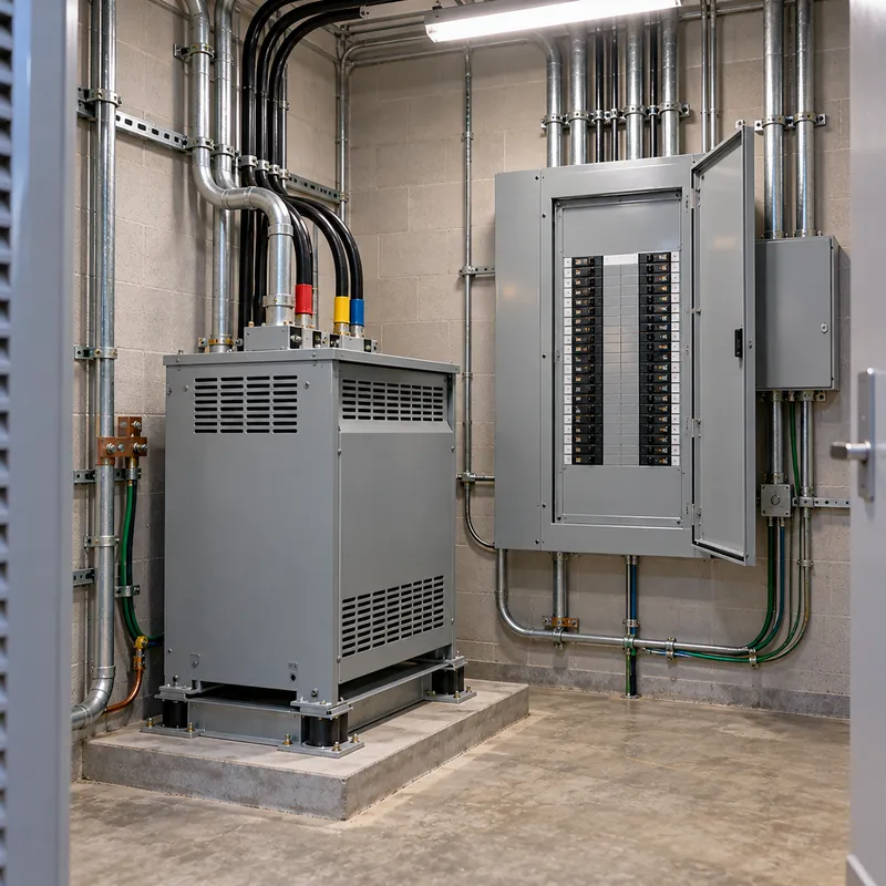
Terminal markings follow the H (high-voltage) and X (low-voltage) convention. For a 277 to 120/240 V unit the secondary often has two 120 V windings that can be paralleled for 120 V two-wire or seriesed for 120/240 V three-wire. Always follow the connection diagram on the nameplate, and have the work done by a licensed electrician to local code.
- De-energize and lock out the 277 V lighting panel circuit and verify absence of voltage.
- Land the 277 V phase conductor on H1 and the neutral on H2 through the primary breaker.
- For 120 V two-wire, parallel the secondary windings (X1 to X3, X2 to X4) and take output from X1 and X4; for 120/240 V, jumper X2 to X3 as the neutral point.
- Install the system bonding jumper from the secondary neutral (X2 or the X2–X3 junction) to the enclosure, at the transformer or first disconnect only.
- Connect the grounding electrode conductor to the building steel or nearest grounding electrode, sized per NEC Table 250.66.
- Run the equipment grounding conductor with the primary circuit, sized per NEC Table 250.122.
- Energize with no load, measure 120 V output, then connect loads and check current against nameplate.
Never connect a 277 V primary between two phases: that applies 480 V and will destroy the transformer. Our transformer hook-up guide shows more connection examples.
Grounding and Neutral Issues on 277 V Primaries
Because the secondary is isolated from the primary, NEC 250.30 treats it as a separately derived system. The 120 V neutral must be bonded to ground at exactly one point. Bonding it at both the transformer and a downstream panel creates parallel neutral current on grounding paths, which shows up as nuisance GFCI trips and measurable neutral-to-ground voltage. Our neutral-to-ground voltage guide explains how to diagnose that problem.
Primary neutral loading
A 277 V primary returns all its current on the 480Y/277 V neutral. If many 277 to 120 transformers sit on the same phase, the neutral at the lighting panel carries the unbalanced sum. Spread units across A, B and C phases so currents largely cancel.
Harmonics
Single-phase electronic loads such as chargers and computers produce third-harmonic current. On the 120 V side this is contained by the transformer, but the transformer itself heats more than with linear loads. For heavily nonlinear loads specify a K-4 or K-13 rating, or derate the unit.
Equipment grounding
Size the primary equipment grounding conductor per NEC Table 250.122 from the primary breaker rating; see our equipment grounding conductor sizing guide. A 50 A breaker needs a 10 AWG copper EGC.
Selecting Insulation, Enclosure and Efficiency
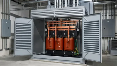
Small 277 to 120 transformers are almost always dry-type. Two construction styles dominate:
- Encapsulated (potted): core and coils filled with resin or compound, typically up to about 25 kVA single-phase, suitable for outdoor NEMA 3R installation and dusty spaces.
- Ventilated: open coils with air cooling, lighter and cooler-running at larger ratings, but needs indoor or protected installation.
Insulation systems are usually 180 °C class with 115 °C rise for encapsulated units, or 220 °C class with 150 °C rise for ventilated units. Our insulation class and temperature guide explains what those ratings mean for life and overload. Isolated windings also attenuate common-mode noise; if that matters for sensitive electronics, ask for an electrostatic shield as discussed in our isolation transformer guide.
In the US, low-voltage dry-type distribution transformers from 15 kVA single-phase upward fall under DOE efficiency rules (10 CFR 431). Smaller units are generally outside that scope, but core and copper losses still matter if the unit runs continuously.
Next Steps: Specifying and Sourcing
Put the following in your specification or RFQ to avoid substitutions and site surprises:
- Rating (kVA), primary 277 V, secondary 120 V or 120/240 V, frequency 60 Hz.
- Taps if needed (for example 2 × 2.5% FCAN and FCBN) and target impedance.
- Construction (encapsulated or ventilated), enclosure rating (NEMA 1, 3R or IP equivalent) and mounting (wall, floor, trapeze).
- Insulation system, temperature rise, K-factor for nonlinear loads and electrostatic shield if required.
- Listing and standards: UL 1561 or UL 5085 as applicable, IEEE C57.12.01 or IEC 60076-11, plus test reports.
- Quantity per phase, so the supplier can mark units for A, B and C distribution.
MARS supplies dry-type transformers in single-phase and three-phase designs for 50 and 60 Hz, built to IEC 60076-11 with ANSI/IEEE variants and routine-tested before shipment. For a larger 120 V requirement, we can also quote a three-phase 480–208Y/120 V unit with matching LV distribution boards. Send voltages, kVA and quantities through our quote form.
Frequently asked questions
Can I get 120V from a 277V circuit?
Yes, with a 277 to 120 transformer connected between the 277 V phase conductor and neutral. You cannot get 120 V by tapping a 277 V circuit to neutral directly. The transformer output is a new separately derived system that must be bonded and grounded at the transformer or first disconnect.
What size breaker do I need for a 10 kVA 277 to 120 transformer?
Primary current is about 36 A. With primary-only protection, NEC 450.3(B) allows 125%, about 45 A, rounded up to 50 A. With a secondary breaker at 125% of 83 A (110 A), the primary breaker may go up to 250%, which helps avoid inrush trips.
Is a 277V to 120V transformer the same as a 480V to 120V transformer?
No. A 277 V primary connects phase-to-neutral and loads one phase plus the neutral. A 480 V primary connects phase-to-phase, needs no neutral and loads two phases. The 480 V version is preferred for larger single-phase loads because it does not add current to the building neutral.
Do LED lights need a 277 to 120 transformer?
Usually not. Most commercial LED drivers accept 120–277 V input, so they run directly on a 277 V lighting circuit. A transformer is needed only when the fixture, sign or control device is rated strictly 120 V. Always check the driver nameplate before buying a transformer.
How do I ground a 120 V transformer secondary?
Treat it as a separately derived system under NEC 250.30. Install one system bonding jumper from the secondary neutral to the enclosure, connect a grounding electrode conductor to building steel or another electrode, and never repeat the neutral-to-ground bond in downstream panels.
How many amps can a 5 kVA 277 to 120 transformer supply?
A 5 kVA unit supplies 5,000 / 120 ≈ 41.7 A at 120 V. For continuous loads, limit the actual load to 80% of that, about 33 A, or size the secondary breaker and conductors at 125% of the continuous load.
Written and reviewed by the MARS application engineering team in Shanghai, who specify and test transformers, switchgear, substations and battery storage for projects in 40+ countries. Last updated .
Tags: 277 to 120 transformer 120 v transformer 277v to 120v transformer 480Y/277 system single-phase dry-type transformer