Key takeaways
- IEC 60085 thermal classes include 105 (A), 120 (E), 130 (B), 155 (F), 180 (H), 200 (N) and 220 (R) degrees Celsius.
- NEMA MG 1 allows an 80 K winding rise for Class B and 105 K for Class F at 40 °C ambient and 1.0 service factor.
- A Class F motor operated at Class B rise keeps about 25 K of thermal margin, which by the 10 K halving rule extends insulation life several-fold.
- IEC 60076-11 limits average winding rise for dry-type transformers to 100 K for Class F (155) and 125 K for Class H (180) systems.
- IEEE C57.91 aging factor rises from 1.0 at a 110 °C hot spot to about 2.7 at 120 °C, so 10 K extra hot spot nearly triples aging.
Quick answer: An insulation class is a thermal rating that states the maximum continuous temperature an insulation system can withstand for its expected life. Under IEC 60085 and NEMA, common classes are B (130 °C), F (155 °C) and H (180 °C). Motors and transformers are designed so ambient plus temperature rise plus hot-spot allowance stays within the class limit.
Heat is the main enemy of electrical insulation. Every motor, generator and transformer has a temperature beyond which its varnish, resin, paper or film degrades too fast to give a useful life. Insulation classes provide a common language for that limit, and they appear on every motor nameplate and dry-type transformer data sheet. Yet the class letter alone does not tell you how hot the equipment will run, or how much life margin it has.
This guide is for engineers, maintenance staff and buyers who specify or compare motors and transformers. It explains the temperature class of insulation under IEC and NEMA, provides a motor insulation class chart, shows why Class F insulation with Class B rise is a common specification, compares dry-type and oil-immersed transformer limits, and works through the aging calculation that links temperature to life.
What Is an Insulation Class?
An insulation class is a classification of an electrical insulation system according to the maximum temperature at which it can operate continuously while achieving an acceptable service life, usually taken as roughly 20,000 hours or more of thermal endurance in accelerated tests. The class applies to the whole system: conductor enamel, slot liners, phase separators, varnish or resin, sleeving and leads, evaluated together.
Insulation classification is defined by IEC 60085 (thermal evaluation and designation), with test methods in IEC 60216 and IEC 61857 for systems, and by UL 1446 in North America. Older letter designations remain in everyday use alongside the numeric classes.
| Thermal class (°C) | Letter | Typical materials |
|---|---|---|
| 90 | Y | Unimpregnated cotton, paper, silk |
| 105 | A | Impregnated cotton and paper, oil-immersed cellulose |
| 120 | E | Polyurethane and epoxy films, some laminates |
| 130 | B | Mica, glass fiber with organic binders, polyester enamels |
| 155 | F | Mica, glass fiber with epoxy or polyester-imide resins |
| 180 | H | Silicone resins, aramid paper, polyimide films |
| 200 | N | Aramid systems, polyimide |
| 220 | R | Aramid and high-temperature resin systems for dry-type transformers |
The class temperature is the hottest-spot limit, not the average winding temperature. Because temperature is never uniform, standards define a permitted average rise plus an allowance for the hot spot.
Motor Insulation Class Chart (NEMA MG 1 and IEC 60034-1)
For electric motors, the permitted winding temperature rise is set by the insulation class, ambient temperature and service factor. NEMA MG 1 and IEC 60034-1 use a 40 °C reference ambient and measure rise by the resistance method. The electric motor insulation class chart below shows typical limits for medium motors.
| Class | Max temperature (°C) | Ambient (°C) | Allowed rise, 1.0 SF (K) | Allowed rise, 1.15 SF (K) | Hot-spot allowance (K) |
|---|---|---|---|---|---|
| A | 105 | 40 | 60 | 70 | 5 |
| B | 130 | 40 | 80 | 90 | 10 |
| F | 155 | 40 | 105 | 115 | 10 |
| H | 180 | 40 | 125 | 135 | 15 |
The structure is simple: class limit = ambient + rise + hot-spot allowance. For Class F: 40 + 105 + 10 = 155 °C. At 1.15 service factor the motor is permitted an extra 10 K, which uses up the hot-spot margin, so continuous operation in the service factor reduces life.
Small motors, totally enclosed non-ventilated designs and special-purpose machines have their own tables in NEMA MG 1, so check the nameplate's stated rise. Our three-phase electric motor guide covers nameplate data more generally.
Effect of altitude and ambient
Rise limits assume altitudes up to 1,000 m. Thinner air cools less effectively, so above 1,000 m either the rise limit or the output is reduced. Likewise, a 50 °C ambient removes 10 K of the available rise unless the motor is derated or uses a higher class.
Class F Insulation with Class B Rise: Why It Is Specified
Class F insulation for motors is now the default for most industrial three-phase machines, but many are designed to run only at Class B temperature rise (80 K). This combination, often written “Class F insulation, Class B rise”, is deliberately conservative.
Worked example: thermal margin
A 75 kW, Class F motor runs at full load with 80 K rise in a 40 °C ambient.
- Hot-spot estimate:
40 + 80 + 10 = 130 °C. - Class F limit: 155 °C.
- Margin:
155 − 130 = 25 K.
Using the widely used rule that insulation life halves for every 10 K increase (derived from the Arrhenius relationship, sometimes called the Montsinger rule), running 25 K below the class limit gives an expected thermal life roughly 2^(25/10) = 2^2.5 ≈ 5.7 times longer than running right at the limit. The rule is approximate, and actual life also depends on vibration, contamination, voltage stress and thermal cycling.
Practical benefits
- Headroom for high ambient, up to about 50–55 °C, without derating.
- Tolerance of voltage unbalance and harmonics, which add heating.
- Capacity to run briefly in the service factor or at high duty cycles.
- Better performance on VFDs, where reduced cooling at low speed and harmonic losses raise temperature.
For inverter-fed motors, thermal class is not the only concern: fast-rising PWM voltage pulses also stress turn insulation, addressed separately by inverter-duty insulation per NEMA MG 1 Part 31 and IEC 60034-18-41. The class F insulation system protects against heat, not against partial discharge from voltage spikes.
Insulation Class in Dry-Type Transformers
Dry-type transformers rely entirely on air and their solid insulation for cooling, so thermal class drives both size and overload capability. IEC 60076-11 links each insulation system temperature to a maximum average winding temperature rise at rated current:
| Insulation system temperature (°C) | Max average winding rise (K) | Typical construction |
|---|---|---|
| 105 (A) | 60 | Rare in modern designs |
| 120 (E) | 75 | Small encapsulated units |
| 130 (B) | 80 | Small and control transformers |
| 155 (F) | 100 | Cast-resin transformers (very common) |
| 180 (H) | 125 | Cast-resin and vacuum-impregnated designs |
| 200 (N) | 135 | Ventilated VPI designs |
| 220 (R) | 150 | Ventilated aramid-insulated designs |
In North America, IEEE C57.12.01 practice is often described by insulation system and rise together, for example a 220 °C system with 150 °C rise, or the same system specified at 115 °C or 80 °C rise. A lower-rise unit has lower load losses and runs cooler, giving built-in overload capacity, at the cost of more copper and core material.
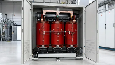
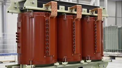
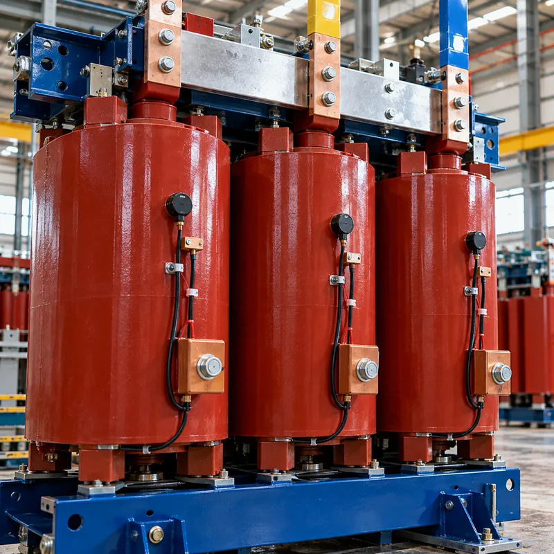
A cast-resin unit with Class F insulation and F rise (100 K) is the most common combination in IEC markets. Specifying Class F insulation but Class B rise (80 K) is a way to buy margin for harmonics, high ambient or future load growth. Our cast resin transformer guide and dry-type transformer guide cover the construction differences, and the K-factor transformer guide explains harmonic heating.
Oil-Immersed Transformers: Temperature Limits Without a Letter
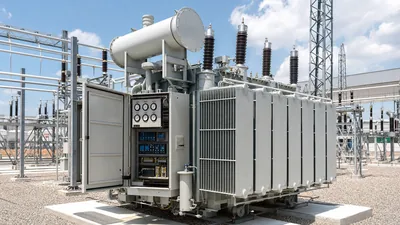
Oil-immersed transformers are not usually described by a letter class. Their solid insulation is oil-impregnated cellulose, and limits are set by temperature rise:
- IEC 60076-2 (ONAN/ONAF): top-oil rise 60 K, average winding rise 65 K, hot-spot rise 78 K, with ambient limits of 40 °C maximum, 30 °C monthly average and 20 °C yearly average.
- IEEE C57.12.00: 65 K average winding rise and 80 K hot-spot rise above a 30 °C average ambient, using thermally upgraded paper with a 110 °C hot-spot reference for normal aging.
The insulation is effectively a 105 °C class system (or 120 °C with thermally upgraded paper) protected by oil, which removes heat far more effectively than air. That is why oil-immersed units are smaller for the same kVA and tolerate overloads well. High-temperature hybrid systems combining aramid paper with ester fluids allow higher rises in compact designs. Our oil-immersed vs dry-type comparison and winding temperature guide cover monitoring and limits in more detail.
For any transformer, the measured winding and oil temperatures are used to estimate hot-spot temperature, which drives aging.
How Temperature Affects Insulation Life: The Aging Calculation
Insulation life follows an Arrhenius relationship: chemical degradation accelerates exponentially with absolute temperature. IEEE C57.91 expresses this for transformer cellulose insulation as an aging acceleration factor relative to a 110 °C reference hot spot:
FAA = exp(15000 / 383 − 15000 / (θH + 273))
where θH is the hot-spot temperature in °C.
Worked example
- Hot spot at 110 °C:
FAA = exp(39.164 − 39.164) = 1.0(normal aging). - Hot spot at 120 °C:
15000 / 393 = 38.168, soFAA = exp(39.164 − 38.168) = exp(0.996) ≈ 2.7. - Hot spot at 98 °C:
15000 / 371 = 40.431, soFAA = exp(−1.267) ≈ 0.28.
A transformer running 10 K hotter ages nearly three times faster; one running 12 K cooler ages at about a quarter of the normal rate. Averaged over a daily load cycle, these factors give equivalent aging, which is the basis of loading guides and overload ratings.
For motor and dry-type insulation, the simpler halving rule (life halves per 8–10 K) gives similar insight. In both cases, the practical message is the same: a few degrees of temperature reduction, achieved by lower rise design, better ventilation or reduced harmonics, buys substantial life. Insulation condition can be tracked with an insulation resistance tester and the methods in our motor insulation test guide.
Choosing the Right Insulation Class
Use these steps to choose insulation class and rise for a motor or dry-type transformer:
- Define ambient and altitude. Maximum and average ambient, ventilation conditions and site altitude above 1,000 m.
- Characterize the load. Continuous, cyclic or peaky; harmonic content; VFD supply; expected growth.
- Pick the class. Class F is the standard choice for industrial motors and cast-resin transformers; Class H or 220 °C systems suit hot environments and compact ventilated designs.
- Pick the rise. Specify a lower rise than the class allows (for example Class B rise on Class F insulation, or 80 K rise on a 220 °C dry-type) when life, harmonics or overload capacity matter.
- Check losses and cost. Lower rise usually means lower load loss and higher purchase price; evaluate total cost of ownership.
- Specify monitoring. PT100 sensors in windings with alarm and trip settings below the class limit.
Remember that class is a system property. Replacing one component, such as rewinding a motor with lower-grade varnish, can reduce the effective class of the whole machine.
Next Steps: Specifying and Sourcing
For dry-type transformers, an RFQ should state insulation system temperature, permitted average winding rise, maximum ambient and altitude, harmonic content or K-factor, enclosure IP rating and the temperature monitoring required (for example three PT100 sensors with a digital relay for fan control, alarm and trip).
MARS manufactures cast-resin dry-type transformers with Class F and Class H insulation systems to IEC 60076-11, with ANSI/IEEE variants, and oil-immersed transformers to IEC 60076-2 temperature limits. Reduced-rise designs can be quoted where you need overload margin, and every unit is routine-tested before shipment, with temperature-rise type test reports available. MARS does not manufacture motors; for motor insulation specifications, follow NEMA MG 1 or IEC 60034-1 with your motor supplier. Send your requirements through the quote request form.
Frequently asked questions
What is the temperature class of insulation?
The temperature class of insulation is the maximum continuous hot-spot temperature an insulation system can tolerate while achieving its expected life. Common classes are A at 105 °C, B at 130 °C, F at 155 °C and H at 180 °C under IEC 60085 and NEMA. Equipment design keeps ambient plus rise plus hot-spot allowance within that limit.
What does Class F insulation mean on a motor?
Class F means the motor's insulation system is rated for a maximum hot-spot temperature of 155 °C. At 40 °C ambient, NEMA MG 1 allows up to 105 K winding rise at 1.0 service factor. Many Class F motors are designed for only 80 K rise, leaving extra thermal margin and extending life.
What is the difference between Class B and Class F insulation?
Class B insulation is rated for 130 °C and allows 80 K rise at 40 °C ambient. Class F is rated for 155 °C and allows 105 K. Class F uses higher-grade resins and binders, tolerates higher ambient and overload, and is the usual industrial default today, often operated at Class B rise for margin.
Which insulation class is used in cast resin transformers?
Cast resin transformers most commonly use Class F (155 °C) insulation with 100 K average winding rise under IEC 60076-11, and some use Class H (180 °C) with 125 K rise. Specifying a Class F system with lower rise, such as 80 K, adds overload and harmonic margin.
How much does temperature reduce insulation life?
As a rule of thumb, insulation life halves for every 8–10 K increase in operating temperature. For transformer cellulose, IEEE C57.91 gives an aging factor of 1.0 at a 110 °C hot spot and about 2.7 at 120 °C, so a 10 K increase nearly triples the aging rate.
Can I run a motor above its insulation class temperature?
Brief excursions cause limited damage, but sustained operation above the class limit rapidly shortens insulation life and can lead to winding failure. If a motor runs hot because of high ambient, unbalance or harmonics, fix the cause, derate it, or replace it with a higher class or lower-rise design.
Written and reviewed by the MARS application engineering team in Shanghai, who specify and test transformers, switchgear, substations and battery storage for projects in 40+ countries. Last updated .
Tags: insulation class temperature class of insulation motor insulation class class f insulation motor insulation class chart