Key takeaways
- Insulation resistance testers apply DC test voltages of 250 V, 500 V, 1 kV, 2.5 kV, 5 kV or 10 kV and report results from kilohms up to several teraohms.
- Polarization index is the 10-minute reading divided by the 1-minute reading; IEEE 43 recommends at least 2.0 for Class B and higher insulation.
- Insulation resistance roughly halves for every 10 °C rise, so readings are corrected to a reference temperature such as 20 °C or 40 °C before comparison.
- The guard terminal diverts surface leakage away from the measurement, which is essential when testing bushings or dirty terminations above about 1 GΩ.
- Oil-impregnated kraft and pressboard insulation in transformers loses resistance sharply with moisture, so IR trends help track paper condition between DP or moisture tests.
Quick answer: An insulation resistance tester applies a stable DC voltage, typically 250 V to 10 kV, across insulation and measures the tiny leakage current to report resistance in megohms or gigohms using R = V / I. It is used to check cables, motors, transformers and switchgear for moisture, contamination and aging without damaging sound insulation.
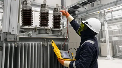
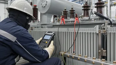
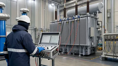
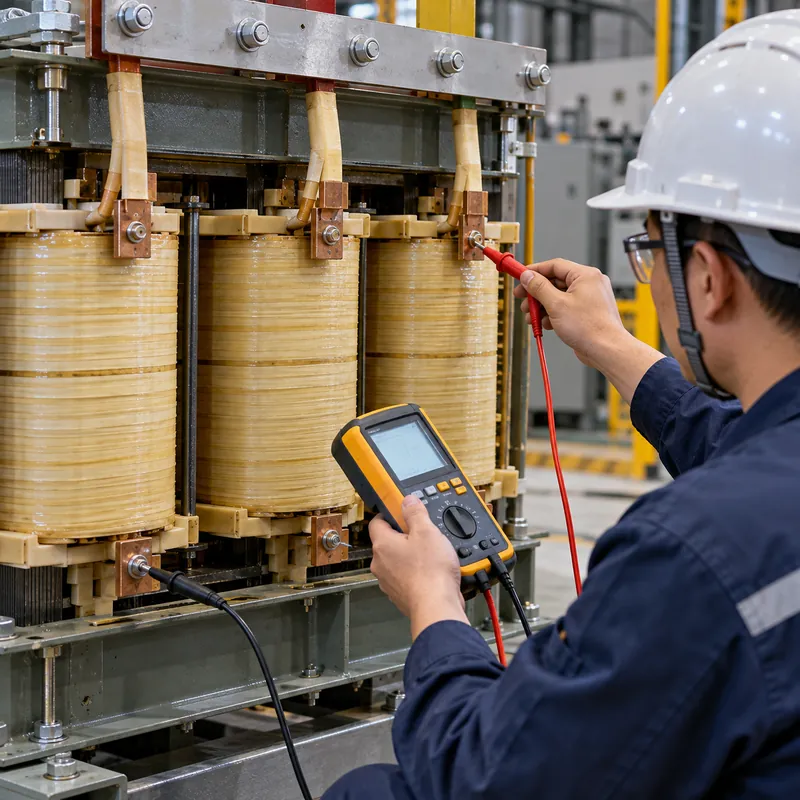
Insulation resistance testing is the most widely performed electrical test in industry. It is quick, non-destructive and works on almost anything with insulation: cables, motors, generators, transformers, switchgear and busbars. The instrument that does it, the insulation resistance tester, ranges from a handheld insulation tester costing less than a multimeter upgrade to a 10 kV, 15 mA diagnostic set for power transformers.
This guide is for maintenance engineers, commissioning technicians and buyers choosing insulation resistance test equipment. It explains how the tester works, how to choose test voltage and range, how to interpret spot, PI and DAR readings, how temperature affects results, and how readings relate to the paper insulation inside oil-filled transformers. For the field procedure itself see our companion guide to checking insulation resistance.
What Is an Insulation Resistance Tester?
An insulation resistance tester (also called an insulation tester, insulation resistance meter or megohmmeter) is an instrument that generates a high DC voltage, applies it across insulation and measures the resulting current to calculate resistance in megohms (MΩ) or gigohms (GΩ). A standard multimeter cannot do this because its ohms range uses only a few volts, far too low to reveal insulation weaknesses.
The current measured has three components:
- Capacitive charging current: high at first, decays within seconds as the insulation charges.
- Absorption (polarization) current: decays over minutes as dielectric molecules align; strong in healthy, dry insulation.
- Conduction (leakage) current: steady current through and across the insulation; rises with moisture, contamination and aging.
Because the first two decay over time, the reported resistance rises during a test. Healthy insulation shows a steadily increasing reading; wet or contaminated insulation plateaus quickly because conduction current dominates.
Types of insulation testers
| Type | Test voltages | Max range (typical) | Typical use |
|---|---|---|---|
| Handheld insulation tester | 50 V – 1 kV | up to about 20–200 GΩ | LV wiring, motors, panels |
| Multifunction installation tester | 250 V – 1 kV | up to about 1 GΩ | Building wiring verification with loop and RCD tests |
| Digital insulation tester, MV | 500 V – 5 kV | up to about 1–10 TΩ | MV cables, switchgear, motors |
| Diagnostic insulation resistance tester | 500 V – 10 kV, step voltage | up to about 20–35 TΩ | Power transformers, generators, HV cables |
| Analog hand-crank tester | 500 V – 1 kV | up to about 2–10 GΩ | Legacy field use |
How to Choose Insulation Tester Test Voltage
Test voltage should stress insulation enough to reveal weakness but not exceed what it is rated to withstand in service. Common practice, drawn from IEEE 43 for rotating machines, ANSI/NETA testing specifications and manufacturer guidance, is:
| Equipment rated voltage | Typical DC test voltage | Notes |
|---|---|---|
| Up to 50 V (electronics, SELV) | 50–100 V | Disconnect sensitive devices |
| 120–240 V wiring and equipment | 250–500 V | Building circuits, controls |
| 400–690 V | 500–1000 V | Motors, LV switchboards, LV transformer windings |
| 1 – 2.5 kV | 1000–2500 V | LV/MV boundary equipment |
| 2.5 – 5 kV | 2500 V | 3.3 kV motors, 4.16 kV systems |
| 5 – 12 kV | 2500–5000 V | 6.6 kV and 11 kV switchgear, cables, transformers |
| Above 12 kV | 5000–10,000 V | 33 kV and above, power transformer windings |
Two other specifications matter as much as voltage:
- Short-circuit current: a large winding or long cable has high capacitance. A tester with only 1 mA output can take minutes to charge it; 3–5 mA or more shortens test time and gives stable PI readings.
- Maximum resistance range: a clean, dry 11 kV transformer winding can read tens of gigohms. A 1 kV handheld that tops out at 10 GΩ will just show “>10 GΩ” and hide trends.
Our insulation testing procedures and standards article lists the standards behind these values in more detail.
Spot Reading, PI and DAR: Interpreting Results
A single reading is only meaningful against a baseline or minimum value. Time-resistance tests are more powerful because they are largely independent of temperature and geometry.
- Spot reading: resistance after 60 s. Compare with factory, commissioning or previous values under similar conditions.
- Polarization index (PI):
PI = R(10 min) / R(1 min). - Dielectric absorption ratio (DAR):
DAR = R(60 s) / R(30 s), a quicker alternative.
| PI | DAR | Insulation condition (general guidance) |
|---|---|---|
| < 1.0 | < 1.0 | Dangerous: investigate before energizing |
| 1.0 – 2.0 | 1.0 – 1.25 | Questionable: likely moisture or contamination |
| 2.0 – 4.0 | 1.25 – 1.6 | Good |
| > 4.0 | > 1.6 | Very good (very high PI on old, dry, brittle insulation can also indicate aging) |
IEEE 43 recommends a minimum PI of 2.0 for Class B, F and H insulation in rotating machines, and minimum one-minute IR of (kV + 1) MΩ for older windings, 100 MΩ for most form-wound windings built after 1970 and 5 MΩ for random-wound machines below 1 kV. If one-minute IR exceeds about 5 GΩ, PI becomes less meaningful.
For motors in particular, our motor insulation test guide and 3 phase motor testing guide show how IR fits with winding resistance and surge tests.
Worked Example: Temperature Correction and PI on a Transformer
A 2,500 kVA, 11/0.415 kV oil-immersed transformer is tested HV to LV+ground at 5 kV DC. Winding temperature is 35 °C. Readings: 1 min = 1.4 GΩ, 10 min = 3.9 GΩ.
- PI:
3.9 / 1.4 = 2.8, within the good range. - Temperature correction to 20 °C. Using the rule of thumb that resistance halves for every 10 °C rise:
R20 = Rt × 2^((t − 20) / 10)=1.4 × 2^(1.5) = 1.4 × 2.83 = 3.96 GΩ. - Compare with factory. The factory test report shows 4.5 GΩ at 20 °C for the same configuration. The corrected field value is about 88% of the factory value, a normal variation given humidity and different instruments.
- Decision: acceptable. Record the result as the new baseline for maintenance trending.
If the corrected reading had been, say, 0.8 GΩ (under 20% of factory) with PI 1.3, that would point to moisture in the oil-paper system, prompting oil moisture analysis and possibly drying before energization.
The halving rule is an approximation; oil-filled transformers and different insulation materials have their own correction curves, and IEEE 43 uses 40 °C as the reference for rotating machines. Use the same correction method consistently so trends remain valid. For other routine checks see our how to test a transformer guide.
Insulation Paper: What the Tester Is Really Measuring in a Transformer
Inside an oil-immersed transformer, most of the solid insulation is cellulose: kraft paper wrapped on conductors, crepe paper on leads, and pressboard for barriers, spacers and cylinders. Insulation paper is a cellulose sheet material, impregnated with transformer oil, that provides dielectric strength between turns, layers and windings. Electrical paper of this kind is chosen for high dielectric strength, good oil absorption and mechanical strength.
| Insulating paper type | Thermal reference | Typical use |
|---|---|---|
| Standard kraft paper | 105 °C class (95 °C hot-spot reference in IEEE loading guides) | Older and some IEC distribution designs |
| Thermally upgraded kraft | 110 °C hot-spot reference, 65 °C average winding rise | Most modern oil-immersed units |
| Pressboard | 105 °C class | Barriers, spacers, winding cylinders |
| Aramid paper | Up to 220 °C class | Dry-type windings, high-temperature hybrid liquid designs |
Insulation resistance in an oil-paper system is dominated by moisture. Water preferentially migrates into cellulose, so a winding whose paper moisture rises from 0.5% to 3% can show IR falling by an order of magnitude. Paper also degrades by depolymerization: new paper has a degree of polymerization (DP) around 1,000–1,200, while DP near 200 is generally considered end of life because the paper loses mechanical strength. IR testers cannot measure DP directly, but a falling trend in corrected IR and PI is an early indicator to schedule oil analysis, including furan testing. Our transformer insulation engineering guide and dielectric insulating oil guide cover the oil-paper system in depth.
Selecting Insulation Resistance Test Equipment
Use this checklist when comparing insulation resistance testers or an insulation resistance test kit:
- Voltages: cover every equipment class you maintain. A 1 kV handheld suits LV; MV and transformer work needs 5 kV or 10 kV.
- Range and accuracy: maximum resistance at each voltage and stated accuracy, usually ±5% over the main range.
- Output current: 2–5 mA for large capacitive loads; check charge time specification.
- Automatic tests: timed PI, DAR, step voltage (SV) and dielectric discharge (DD) for diagnostic work.
- Guard terminal: essential for accurate readings above about 1 GΩ.
- Safety rating: IEC 61010 measurement category, for example CAT IV 600 V for handhelds used near service equipment, live-circuit warning and automatic discharge.
- Noise rejection: substations have induced AC and DC interference; specify the rated noise rejection (for example several mA at 50/60 Hz).
- Data: internal memory, download software or a test-record interface so results feed maintenance trending.
A digital insulation resistance tester with timed tests is preferred over analog for most new purchases. Pair it with a winding resistance meter and turns ratio tester for full transformer diagnostics, as described in our transformer testing equipment guide. For pass/fail proof testing at higher voltages, a hipot set is a separate instrument; see our dielectric withstand test guide.
Using the Guard Terminal Correctly
Most MV and diagnostic insulation testers have three terminals: positive (+), negative (−) and guard (G). The guard is held at the same potential as one test terminal, so any current flowing across a surface path connected to it bypasses the measuring circuit.
Example: when testing a transformer HV winding to tank, surface leakage along a damp, dirty bushing flows from the HV terminal to the grounded flange. That current adds to the bulk insulation leakage and lowers the reading. Wrapping a bare conductor around the bushing porcelain near the top, connected to the guard, intercepts the surface current. The tester then reports only the bulk insulation resistance.
Typical guard uses:
- Bushings and post insulators with surface contamination.
- Three-winding or multi-winding transformers, to isolate one insulation path (for example HV to LV with the tank guarded).
- Cables, guarding the termination surface so only the main insulation is measured.
Note that a guarded measurement shows a different value from an unguarded one, so record the configuration with every reading. Power factor (tan δ) testing uses similar guard techniques; see our power factor test guide.
Next Steps: Specifying and Sourcing
MARS does not manufacture or sell insulation resistance testers or other test instruments. We use them every day: insulation resistance between windings and to ground is part of the routine tests performed on every MARS transformer and switchgear panel before shipment, with results recorded on the test report you receive.
When ordering power transformers or oil-immersed distribution transformers, ask for:
- Factory IR values at a stated test voltage and temperature, for each winding combination.
- PI or DAR values for larger units.
- The temperature correction method used, so site readings can be compared directly.
- Oil moisture content and, for power transformers, a dryness statement for the solid insulation.
These give your commissioning team a firm baseline. Send your specification through the quote request form, and our engineers will confirm test reports included with the supply.
Frequently asked questions
What does an insulation resistance tester measure?
It measures the electrical resistance of insulation by applying a high DC voltage, typically 250 V to 10 kV, and measuring the small current that leaks through and across it. The result is shown in megohms or gigohms. Higher values indicate cleaner, drier insulation; falling values over time indicate moisture, contamination or aging.
What is a good insulation resistance reading?
It depends on equipment and voltage. IEEE 43 suggests at least 5 MΩ for random-wound motors under 1 kV and 100 MΩ for most form-wound windings. Transformers and cables are judged against factory and previous values corrected to the same temperature. A polarization index above 2.0 indicates healthy insulation.
What voltage should I use for insulation resistance testing?
Use 500 V DC for 120–240 V equipment, 500–1000 V for 400–690 V motors and switchboards, 2500 V for 2.5–5 kV equipment, and 5 kV or 10 kV for 11 kV class and above. Never exceed the voltage the equipment or connected electronics are rated to withstand.
Can I use a multimeter instead of an insulation tester?
No. A multimeter's resistance range uses only a few volts and cannot reveal insulation weaknesses that appear at operating voltages. It may show open circuit on insulation that would break down at 480 V. Use an insulation tester with an appropriate DC test voltage for meaningful results.
Why does insulation resistance change with temperature?
Insulation materials conduct more as temperature rises because ions and moisture become more mobile. As a rule of thumb, resistance halves for every 10 °C increase. Readings must be corrected to a common reference temperature, such as 20 °C or 40 °C, before comparing them with earlier tests.
What is the difference between a handheld and a diagnostic insulation tester?
A handheld insulation tester usually tests up to 1 kV with ranges to tens or hundreds of gigohms and suits LV wiring and motors. A diagnostic tester reaches 5 or 10 kV, measures into teraohms, supplies more charging current and runs PI, step-voltage and dielectric discharge tests for transformers and HV equipment.
Written and reviewed by the MARS application engineering team in Shanghai, who specify and test transformers, switchgear, substations and battery storage for projects in 40+ countries. Last updated .
Tags: insulation resistance tester insulation tester digital insulation resistance tester insulation resistance test equipment insulation paper