Key takeaways
- A dielectric withstand test applies elevated AC or DC voltage, commonly for 60 seconds, and passes if there is no breakdown and leakage stays below the trip setting.
- A widely used appliance formula is 2 × rated voltage + 1000 V, so 480 V equipment is tested at about 1960 V AC for one minute.
- IEC 60076-3 assigns power-frequency withstand levels by Um, for example 28 kV for 12 kV equipment and 50 kV for 24 kV equipment.
- DC hipot voltages are typically about 1.414 times the AC RMS value to match the AC peak stress, but DC stresses insulation differently.
- Charging current I = 2πfCV sets test-set size; 5 nF of winding capacitance at 28 kV and 50 Hz draws about 44 mA, roughly 1.2 kVA.
Quick answer: A dielectric withstand test, or hipot test, applies a voltage well above normal operating voltage between live parts and ground for a set time, typically 60 seconds, to prove the insulation will not break down. It is a pass/fail test: the item passes if no flashover occurs and leakage current stays below the set trip limit.
Insulation is the part of electrical equipment that fails silently. A transformer, switchboard or cable can measure perfectly on a resistance test and still contain a void, a contaminated creepage surface or an inadequate clearance that only reveals itself during a lightning surge or switching transient. The dielectric withstand test exists to find those weaknesses before the equipment goes into service, by deliberately stressing insulation beyond its working voltage under controlled conditions.
This guide is for test engineers, quality inspectors and buyers witnessing factory tests. It explains what a hipot test is, how AC and DC methods differ, how test voltages are set under IEC, IEEE and UL standards, how the test is applied to transformers, and a safe step-by-step procedure. It complements our insulation resistance tester guide, which covers the non-destructive DC megohm test.
What Is a Hipot Test in Electrical Engineering?
A hipot test (short for high-potential test) is a dielectric voltage withstand test in which a voltage several times higher than rated is applied across insulation to confirm it can withstand overvoltages without breakdown. The terms hipot test, dielectric withstand test, dielectric voltage withstand test, applied voltage test and dielectric strength test are used almost interchangeably in industry.
Strictly, two related but different things are measured:
- Withstand test: applies a specified voltage for a specified time and checks the insulation survives. It is a proof test and the voltage is chosen to be safely below the insulation's actual breakdown strength.
- Breakdown (dielectric strength) test: raises voltage until the material fails, used on samples such as transformer oil or insulating paper to measure dielectric strength in kV/mm. Oil breakdown voltage per IEC 60156 is an example.
A withstand test is performed on finished products as a routine or type test. It verifies dielectric integrity: adequate clearance and creepage distances, absence of pinholes and contamination, and correct assembly. It does not measure how good the insulation is, only that it is good enough at the test level.
Hipot testing is mandatory in most product standards: IEC 61439 for LV switchgear assemblies, IEC 62271-1 and -200 for MV switchgear, IEC 60076-3 and IEEE C57.12.90 for transformers, and UL safety standards for appliances and industrial equipment.
AC vs DC Hipot: Which Dielectric Voltage Test to Use?
Both AC and DC high potential testers are common. The choice depends on the equipment, the standard and whether the test is in a factory or the field.
| Factor | AC hipot | DC hipot |
|---|---|---|
| Stress distribution | Matches service conditions (capacitive) | Distributed by resistance; differs from service |
| Typical test voltage | Specified RMS value | About 1.414 × AC RMS (peak equivalent) |
| Test-set size for capacitive loads | Large: must supply charging current | Small: only leakage current after charging |
| Leakage reading | Includes capacitive current; harder to interpret | Pure leakage; trend useful for diagnostics |
| Standards preference | Factory routine tests on transformers and switchgear | Some cable and rotating-machine field tests |
| Discharge after test | Minimal stored charge | Must be grounded long enough to discharge |
For transformers and MV switchgear, standards specify AC power-frequency tests, and DC is generally not an acceptable substitute in the factory. For extruded-dielectric cables, DC field testing has largely been replaced by very low frequency (VLF, typically 0.1 Hz) AC testing under the IEEE 400 series, because DC can leave space charge that later contributes to failure.
Charging current matters in AC testing. It equals I = 2π × f × C × V. A long cable or large winding can need tens or hundreds of milliamps, which is why a high-capacity test transformer or resonant test system is used for large items; see our high-voltage test transformer guide.
Dielectric Strength Test Voltage: How Levels Are Set
The test voltage depends on the product standard and the equipment's rated or highest voltage. For low-voltage equipment, a long-established formula used in many UL and IEC appliance and equipment standards is:
Vtest = 2 × Vrated + 1000 V (AC, 60 s)
Production lines often use a shortened test of 1 to 2 seconds at 120% of the one-minute value, where the standard allows it.
For MV equipment, the test level is tied to the highest voltage for equipment, Um. Standard insulation levels come from IEC 60071-1 and are applied in IEC 60076-3 for transformers and IEC 62271-1 for switchgear. Typical values are:
| Um (kV rms) | Typical system voltage | Short-duration power-frequency withstand (kV rms) | Lightning impulse withstand (kV peak) |
|---|---|---|---|
| 1.1 | 400–690 V | 3 | — |
| 3.6 | 3.3 kV | 10 | 40 |
| 7.2 | 6–6.6 kV | 20 | 60 |
| 12 | 10–11 kV | 28 | 75 |
| 17.5 | 15 kV | 38 | 95 |
| 24 | 20–22 kV | 50 | 125 |
| 36 | 33–35 kV | 70 | 170 |
| 72.5 | 66 kV | 140 | 325 |
| 123 | 110 kV | 230 | 550 |
Some Um values have more than one standardized insulation level, and North American equipment uses BIL classes under IEEE C57.12.00 and IEEE C37 standards, so always take the exact value from the specification and nameplate. Insulation coordination concepts are summarized in our voltage classes guide.
Worked Example: Test Voltage and Test-Set Sizing
Case 1: 480 V control panel. Using the formula approach: 2 × 480 + 1000 = 1960 V AC for 60 seconds. A production 1-second test at 120% would be 1.2 × 1960 = 2352 V. If a DC test is permitted, the peak-equivalent value is 1960 × 1.414 ≈ 2771 V DC. Always confirm against the governing product standard, since IEC 61439-1 tabulates its own values by rated insulation voltage.
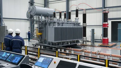
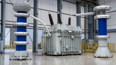
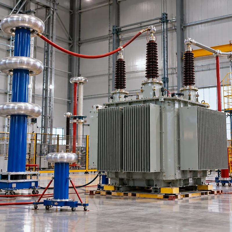
Case 2: 11 kV transformer HV winding. With Um = 12 kV, IEC 60076-3 specifies a separate-source AC withstand of 28 kV for 60 s between the HV winding (all terminals shorted together) and the LV winding plus core and tank (grounded).
- Measured HV-to-ground capacitance: 5 nF.
- Charging current at 50 Hz:
I = 2π × 50 × 5 × 10⁻⁹ × 28,000 = 0.044 A, or 44 mA. - Test-set output:
28 kV × 0.044 A ≈ 1.23 kVA; a 5 kVA, 50 kV test transformer gives comfortable margin. - Trip setting: set above the capacitive current, for example 60–80 mA, so a genuine breakdown trips but charging current does not.
The same calculation at 60 Hz gives 53 mA. For a 33 kV winding at 70 kV with 10 nF, current is about 220 mA and the test set needs roughly 15 kVA, which explains why large transformer test bays use dedicated high-voltage test transformers or resonant systems.
How Transformers Are Dielectric Tested
Transformers receive a combination of dielectric tests because no single test stresses every part of the insulation. The main ones under IEC 60076-3 and IEEE C57.12.90 are:
- Separate-source AC withstand (applied voltage) test: each winding, shorted on itself, is tested to the others and ground. It checks major insulation between windings and to the core and tank, but not turn-to-turn insulation, because the whole winding is at one potential.
- Induced voltage test: the LV winding is excited at about twice rated voltage, using a raised frequency (often 100–400 Hz) so the core does not saturate. This stresses turn-to-turn, layer and phase-to-phase insulation. For higher-voltage units it is combined with partial discharge measurement (IVPD).
- Lightning impulse test: a 1.2/50 μs impulse at the BIL level, a type or special test for distribution units and routine for larger power transformers.
- Switching impulse test: for EHV units.
Before and after dielectric tests, insulation resistance and often power factor (tan δ) are measured to confirm nothing changed. Our power transformer testing guide places these in the full routine-test sequence, and partial discharge testing explains why PD measurement complements a pass/fail withstand.
Field tests on transformers in service, where performed, use reduced voltage, commonly around 75–80% of the factory level, to avoid cumulatively damaging aged insulation.
Dielectric Withstand Test Procedure: Step by Step
High-voltage testing must be carried out only by trained, authorized personnel inside a controlled test area, following NFPA 70E or the local equivalent and the test-set manufacturer's instructions. The general sequence for an AC withstand test is:
- Prepare the area. Barricade the test zone, post warning signs, verify interlocks and emergency stop, and confirm a clear line of sight.
- Prepare the item. Disconnect or remove surge arresters, electronics, VTs and anything not rated for the test voltage. Short together all terminals of the winding or circuit under test; ground all others plus the frame.
- Measure insulation resistance first. A low IR reading suggests moisture or contamination; resolve it before applying high voltage.
- Connect the tester. High-voltage lead to the shorted circuit under test, return to ground. Keep leads clear of other objects.
- Set limits. Program test voltage, ramp rate, dwell time and leakage trip current per the standard.
- Ramp up. Raise voltage smoothly, commonly reaching full value within 10–15 seconds, starting no higher than about one-third of test voltage.
- Hold. Maintain full voltage for the specified time, typically 60 s, observing current and listening for discharge.
- Ramp down and discharge. Reduce voltage to below one-third before switching off, then apply a grounding stick. For DC tests, keep grounded for several times the test duration.
- Re-measure IR and record. Document test voltage, duration, leakage, ambient conditions and result.
Pass criteria are no disruptive discharge, no collapse of voltage and leakage below the trip limit. Our insulation testing procedures and standards article compares hipot with other insulation tests.
Choosing a Dielectric Strength Tester
A dielectric strength tester, or high potential tester, is selected by output, waveform and safety features. Key specifications are:
- Output voltage and type: AC, DC or both; for LV product lines 5 kV AC / 6 kV DC is typical, while MV equipment needs 50–100 kV AC test sets.
- Output current or kVA: enough to supply charging current at test voltage, as calculated above.
- Leakage measurement: resolution and adjustable trip limits; real (resistive) current separation helps on capacitive loads.
- Ramp, dwell and arc detection: programmable timing and fast arc detection for production use.
- Safety: zero-start interlock, external interlock input, automatic discharge, hand-held HV probe with dead-man switch, compliance with IEC 61010 for test equipment.
- Data: stored results and serial or network interface for traceability.
For factory transformer testing, the test system is part of a laboratory setup with calibrated voltage dividers. See our transformer testing equipment guide for an overview of the full instrument set.
Next Steps: Specifying and Sourcing
When buying transformers or switchgear, the dielectric test requirements belong in the specification, not just the inspection plan. Include:
- Um and insulation level for each winding or circuit (power-frequency and lightning impulse values).
- Required tests and whether they are routine, type or special (for example applied voltage, induced voltage with PD, lightning impulse).
- Standard and edition (IEC 60076-3, IEEE C57.12.90, IEC 62271-1, IEC 61439-1).
- Witness points and document requirements for FAT, and any reduced-voltage field tests planned at site acceptance.
MARS performs routine dielectric tests on every power transformer, distribution transformer and switchgear panel we build, to IEC with ANSI/IEEE and GB variants, and FAT witnesses are welcome. For what to check during witnessed testing see our transformer FAT checklist and, after delivery, our site acceptance test guide. Send your specification through the quote request form.
Frequently asked questions
What is a hipot test in electrical?
A hipot test applies a high voltage, well above normal operating voltage, between energized conductors and ground or between isolated circuits to prove the insulation can withstand overvoltage. If no breakdown occurs and leakage current stays under a set limit for the test time, usually 60 seconds, the item passes.
What is the difference between a hipot test and an insulation resistance test?
An insulation resistance test applies a moderate DC voltage, such as 500 V to 5 kV, and measures resistance in megohms; it is diagnostic and non-destructive. A hipot test applies a much higher voltage to prove withstand capability and is pass/fail. IR is usually measured before and after a hipot test.
How is hipot test voltage calculated?
For many low-voltage products the test voltage is twice the rated voltage plus 1000 V AC for one minute, so 230 V equipment is tested at 1460 V. Medium-voltage equipment uses tabulated levels based on the highest voltage for equipment, such as 28 kV for 12 kV class under IEC 60076-3.
Is a dielectric withstand test destructive?
It is designed not to damage sound insulation, because the test voltage is set below the material's breakdown strength. However, it can damage insulation that is already weak, and repeated testing can cause cumulative degradation. That is why field retests on aged equipment use reduced voltages, often 75–80% of factory values.
What leakage current is acceptable in a hipot test?
The limit depends on the standard and the item's capacitance. For small LV products, trip limits of a few milliamps are common. For transformers and cables, AC charging current can be tens of milliamps, so the limit is set just above expected charging current and the main pass criterion is absence of breakdown.
Can I use DC instead of AC for a hipot test?
Some standards permit DC at about 1.414 times the AC RMS value, which matches the peak voltage. Factory tests on transformers and MV switchgear usually require AC. DC is less representative for capacitive insulation and is no longer preferred for aged extruded cables, where VLF AC testing is common.
Written and reviewed by the MARS application engineering team in Shanghai, who specify and test transformers, switchgear, substations and battery storage for projects in 40+ countries. Last updated .
Tags: dielectric withstand test hipot test dielectric voltage withstand test dielectric strength tester dielectric withstand test procedure