Key takeaways
- Phase-to-phase winding resistance on a healthy three-phase motor typically agrees within about 2–5%; larger imbalance suggests shorted turns or a loose connection.
- A multimeter can check continuity and balance, but readings below about 1 Ω need a four-wire low-resistance ohmmeter for meaningful accuracy.
- IEEE 43 suggests a minimum insulation resistance of 5 MΩ for random-wound motors under 1 kV, tested at 500 V DC and corrected to 40 °C.
- NEMA MG 1 defines voltage unbalance as maximum deviation from average divided by average; added heating is roughly twice the square of percent unbalance.
- Resistance should be corrected to a common temperature using R25 = Rm × (234.5 + 25) / (234.5 + tm) for copper windings before comparing tests.
Quick answer: To test a 3 phase motor, isolate and lock it out, then measure winding resistance between each pair of leads (readings should match within about 2–5%), measure insulation resistance from windings to frame with a 500 V or 1000 V DC insulation tester, and finally check running current and supply voltage balance under load.
When a three-phase motor trips, hums, runs hot or will not start, the first question is whether the motor itself is faulty or the problem lies in the supply, starter or load. A short sequence of tests, most of them done with a multimeter and an insulation resistance tester, answers that question in under an hour and avoids sending a healthy motor for rewind.
This guide is for maintenance electricians, plant engineers and technicians. It covers how to check a 3 phase motor safely, how to ohm out windings with a multimeter, what winding resistance values to expect, how to perform an insulation resistance test, and the running checks that reveal supply problems. Work on motors and their supply circuits must follow local code and lockout rules and be performed by qualified electrical personnel.
3 Phase Motor Testing Methods at a Glance
No single test proves a motor healthy. Each method targets a different failure mode, so use them in sequence from simplest to most specialized.
| Test | Instrument | Detects | Motor state |
|---|---|---|---|
| Visual and mechanical | Eyes, hands, nose | Burn marks, seized bearings, damaged leads | De-energized |
| Continuity and winding resistance | Multimeter or low-resistance ohmmeter | Open windings, shorted turns, bad connections | De-energized |
| Insulation resistance and PI | Insulation resistance tester (500–5000 V DC) | Ground faults, moisture, contamination | De-energized |
| Surge comparison | Surge tester | Weak turn-to-turn insulation | De-energized |
| Running current and voltage | Clamp meter, multimeter | Overload, unbalance, single-phasing | Running |
| Vibration and temperature | Vibration meter, infrared thermometer | Bearing wear, misalignment, cooling faults | Running |
The first three tests can be done in the field with common instruments and catch the large majority of electrical faults. Surge testing (IEEE 522 covers turn insulation test levels for form-wound coils) and motor current signature analysis are specialist methods normally used by motor repair shops or reliability teams.
For background on motor construction and nameplate data see our three-phase electric motor guide.
Before You Test: Safety and Disconnection
Motor testing begins with isolation, not with the meter. Follow your site's electrical safety program, NFPA 70E or the local equivalent:
- Identify the motor and its starter, drive or MCC bucket from the drawings and labels.
- Stop the motor and open the disconnecting means; apply lockout and tagout.
- Verify absence of voltage at the motor terminals with a properly rated, proven tester.
- Discharge any power-factor correction capacitors connected at the motor.
- Disconnect the motor leads from the supply cables in the terminal box, so that tests measure only the motor. Mark leads (T1, T2, T3 or U1, V1, W1) before separating them.
- If a VFD is connected, disconnect it before any insulation test: the DC test voltage can destroy drive electronics.
Testing from the starter end with the cable connected is a quick first check, but a low reading must then be traced to either cable or motor by separating them. Our motor control center guide describes the bucket layouts where these disconnections are usually made.
Record nameplate data before starting: voltage, full-load current, power, connection (star or delta, 6, 9 or 12 lead), insulation class and service factor. These determine what readings to expect.
How to Test a 3 Phase Motor With a Multimeter
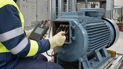
A digital multimeter can check continuity and compare the three windings. Here is how to ohm out a 3 phase motor with three external leads:
- Set the meter to its lowest resistance range and short the probes together; note the lead resistance (often 0.1–0.3 Ω) and subtract it from readings, or use the meter's relative/zero function.
- Measure T1–T2, T2–T3 and T1–T3. Each reading should be low and nearly equal.
- Measure each lead to the motor frame. The meter should show open circuit (OL). Any reading here indicates a ground fault, to be confirmed with an insulation tester.
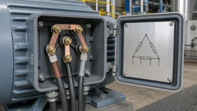
- For 6-lead motors, measure each winding separately: U1–U2, V1–V2, W1–W2, then check there is no continuity between windings.
- For 9- and 12-lead motors, identify the winding groups from the connection diagram and compare corresponding groups.
Interpreting multimeter results
- Open (OL) between two leads: broken winding, failed internal connection or burnt lead.
- One reading noticeably lower: possible shorted turns in that phase.
- All readings equal and low: windings likely intact, but a multimeter cannot detect weak insulation or a few shorted turns in a large motor.
Testing motors with a multimeter has a resolution limit. On motors above roughly 10–20 kW, phase resistance can be well under 1 Ω, comparable to the meter's own lead resistance and accuracy. A four-wire (Kelvin) low-resistance ohmmeter or micro-ohmmeter is needed for reliable comparison. The connection diagrams in our 3 phase motor wiring diagrams guide help identify lead groups.
3 Phase Motor Winding Resistance Values and Balance
There is no universal motor winding resistance chart, because resistance depends on power, voltage, speed and design. The table gives indicative order-of-magnitude values for 400–480 V, four-pole, low-voltage induction motors measured phase-to-phase. Always compare against the manufacturer's data or the motor's own previous readings.
| Motor rating | Indicative phase-to-phase resistance | Suitable instrument |
|---|---|---|
| 0.37–2.2 kW (0.5–3 hp) | about 3–40 Ω | Multimeter |
| 3–11 kW (4–15 hp) | about 0.5–4 Ω | Multimeter, preferably low-resistance ohmmeter |
| 15–55 kW (20–75 hp) | about 0.05–0.6 Ω | Low-resistance ohmmeter |
| Above 75 kW (100 hp) | below about 0.05 Ω | Micro-ohmmeter (four-wire) |
Star vs delta readings
Phase-to-phase readings differ from per-phase winding resistance. In a star (wye) connection, R(L-L) = 2 × R(phase). In a delta, one winding is in parallel with the other two in series, so R(L-L) = (2/3) × R(phase). This matters when comparing a motor reconnected from star to delta. See our star-delta connection guide for the connection details.
Temperature correction
Copper resistance rises about 0.39% per °C. To compare readings taken at different temperatures, correct to 25 °C: R25 = Rm × (234.5 + 25) / (234.5 + tm). A winding measured at 0.450 Ω while still warm at 55 °C corrects to 0.450 × 259.5 / 289.5 = 0.403 Ω.
Worked Example: Checking Motor Winding Resistance Balance
A 30 kW, 400 V, delta-connected motor trips on overload. A four-wire low-resistance ohmmeter at 20 °C gives:
- T1–T2: 0.412 Ω
- T2–T3: 0.418 Ω
- T1–T3: 0.405 Ω
Average: (0.412 + 0.418 + 0.405) / 3 = 0.4117 Ω
Maximum deviation: 0.418 − 0.4117 = 0.0063 Ω
Imbalance: 0.0063 / 0.4117 × 100 = 1.5%
An imbalance of 1.5% is within the 2–5% range commonly regarded as acceptable for low-voltage motors, and many repair shops target under 2% for new or rewound motors. The windings appear sound, so the overload cause is more likely mechanical load, supply voltage or a starter fault, and the next step is insulation and running tests.
Had T2–T3 read 0.370 Ω while the others read about 0.41 Ω, imbalance would be about 7%, consistent with shorted turns in the winding connected directly between T2 and T3. Because each phase-to-phase reading in a delta involves all three windings, confirm by opening the delta (on 6-lead motors) and measuring each winding separately.
Trend these values. A motor whose readings drift apart over successive tests is developing a problem even if each reading still passes. The same balance principle is used for transformers, as shown in our transformer winding resistance test guide.
How to Perform an Insulation Resistance (Megohmmeter) Test on a 3 Phase Motor
The insulation resistance test, often called megohmmeter testing, checks the insulation between windings and the grounded frame. It is the most important test for detecting moisture and ground faults.
- With leads disconnected from the supply, connect T1, T2 and T3 together (for a quick all-windings-to-ground test).
- Connect the insulation tester's positive or line lead to the joined windings and the earth lead to a clean, bare spot on the frame.
- Select test voltage per IEEE 43: 500 V DC for motors rated below 1000 V, 500–1000 V for 1000–2500 V, 1000–2500 V for 2501–5000 V.
- Apply the voltage for 1 minute and record the reading and winding temperature.
- For motors with accessible winding ends, also test phase-to-phase by separating windings.
- For larger motors, continue to 10 minutes and calculate the polarization index,
PI = R10 / R1. - After the test, ground the windings for at least as long as the test voltage was applied to discharge them.
IEEE 43 minimums, corrected to 40 °C, are 5 MΩ for random-wound motors below 1 kV and 100 MΩ for most form-wound windings; PI should be at least 2.0 for Class F insulation. Readings of a few hundred megohms or more are typical for clean, dry LV motors. Our insulation resistance tester guide covers instrument selection, and the motor insulation test guide explains trend interpretation.
Running Tests: Current, Voltage Unbalance and Rotation
If the motor passes static tests, check it under load. Many motor failures are caused by supply problems.
Voltage unbalance
Measure line-to-line voltage at the motor terminals. NEMA MG 1 defines:
% unbalance = 100 × (max deviation from average) / average
Example: 398 V, 404 V and 389 V. Average = 397 V. Max deviation = 397 − 389 = 8 V. Unbalance = 8 / 397 = 2.0%. The approximate added winding temperature rise in percent is 2 × (% unbalance)² = 2 × 2.0² = 8%. NEMA MG 1 recommends derating motors operated above 1% unbalance and advises against operation above 5%.
Current balance
Measure each line current with a clamp meter. Current unbalance is typically several times the voltage unbalance because of the motor's low negative-sequence impedance. Compare against nameplate full-load current; sustained current above nameplate (or above nameplate × service factor) indicates overload.
Single-phasing and rotation
- One line with zero current means single-phasing: a blown fuse, failed contactor pole or broken cable.
- Confirm rotation direction before coupling to the load; see our phase rotation guide.
A motor that passes all static tests but shows unbalanced currents on a balanced supply may have rotor bar damage, best confirmed by current signature analysis.
Next Steps: Specifying and Sourcing
Motor reliability depends heavily on the supply and protection upstream. If testing reveals persistent voltage unbalance, poor regulation or nuisance tripping, the fix is often in the distribution system rather than the motor:
- Balance single-phase loads across phases and check transformer tap settings and impedance.
- Verify overload relay settings and class against nameplate current and starting duty.
- Consider replacing aged MCC buckets or starters with modern, type-tested assemblies to IEC 61439 with motor protection relays providing unbalance and ground-fault functions.
MARS does not manufacture motors or sell stand-alone motor starters. We design and build MV and LV switchgear, including IEC 61439 GGD, GCS and MNS low-voltage boards used as motor control and distribution centers, and the distribution transformers that feed them. Our guides on motor starter types and star-delta starters cover starting methods. Send your single-line diagram and load list through the quote request form.
Frequently asked questions
How do you check a 3 phase motor with a multimeter?
Lock out the supply, disconnect the motor leads and set the meter to its lowest ohms range. Measure T1–T2, T2–T3 and T1–T3; readings should be low and nearly equal. Then measure each lead to the frame, which should read open. Unequal or open readings indicate winding faults.
What should the resistance be on a 3 phase motor?
It depends on size and design. Small motors under 2 kW may read several ohms to tens of ohms phase-to-phase, while motors above 50 kW read well under 0.1 Ω. What matters most is that the three readings are balanced within about 2–5% and consistent with previous tests.
How do you do a megohmmeter test on a 3 phase motor?
Disconnect the motor from its supply and any drive, join T1, T2 and T3, and connect the insulation tester between the joined leads and the motor frame. Apply 500 V DC for motors below 1 kV for one minute, record the reading, then discharge the windings. IEEE 43 suggests at least 5 MΩ.
How do you know if a 3 phase motor is bad?
Signs of a bad motor include an open or unbalanced winding resistance, insulation resistance below the IEEE 43 minimum or a polarization index below 2, ground continuity on a multimeter, burnt smell or discolored windings, and unbalanced currents on a balanced supply. Confirm supply and starter health before condemning the motor.
What is a good insulation resistance reading for a 480V motor?
IEEE 43 sets a minimum of 5 MΩ at 40 °C for random-wound motors below 1 kV when tested at 500 V DC. In practice, clean and dry 480 V motors usually read hundreds of megohms to several gigohms. A falling trend between tests is a warning even if values remain above the minimum.
Can a motor pass a resistance test and still be bad?
Yes. A multimeter cannot detect weak turn insulation, minor insulation degradation or rotor bar faults. A motor can show balanced resistance and still fail under voltage stress or load. Insulation resistance, surge comparison and running current tests are needed for a complete assessment.
Written and reviewed by the MARS application engineering team in Shanghai, who specify and test transformers, switchgear, substations and battery storage for projects in 40+ countries. Last updated .
Tags: how to test a 3 phase motor how to test a 3 phase motor with a multimeter 3 phase motor winding resistance values testing motor windings 3 phase motor testing methods