Key takeaways
- Phase rotation is the order the three phases peak, 120° apart; swapping any two of L1, L2 and L3 reverses the sequence and motor direction.
- A phase sequence indicator connects to all three lines and shows clockwise for L1-L2-L3 positive sequence and counterclockwise for reversed sequence.
- Voltage unbalance per NEMA MG 1 is maximum deviation from average divided by average; above 1% motors need derating and above 5% operation is not recommended.
- Transformers preserve phase sequence but shift phase angle by their vector group, such as 30° lag on the LV side of a Dyn1 unit.
- Before paralleling two sources, both rotation and phasing must match, confirmed by near-zero voltage between like phases across the open tie.
Quick answer: Phase rotation, or phase sequence, is the order in which the three phase voltages reach their peaks, either A-B-C (positive) or A-C-B (negative). It sets the direction of three-phase motors and must match before transformers, generators or utility sources are paralleled. It is checked with a phase sequence indicator connected to L1, L2 and L3; swapping any two phases reverses it.
A three-phase supply can be perfectly healthy on every voltage reading and still be wrong. If the sequence of phases is reversed, pumps run backwards, compressors can be damaged within seconds, fans move air the wrong way and an attempt to parallel two sources produces a phase-to-phase short circuit. Phase rotation is one of the simplest checks in commissioning and one of the most expensive to skip.
This article is for commissioning engineers, electricians and plant maintenance staff. It explains what phase rotation and phase sequence mean, how to identify three-phase power, how to test 3 phase voltage and rotation safely, how transformers affect sequence and phase angle, and what to record when a new transformer or substation is energized.
What Is Phase Rotation and Phase Sequence?
Phase sequence is the order in which the voltages of a three-phase system pass through their positive peaks. With phases labelled A, B and C (or L1, L2, L3), positive sequence A-B-C means B peaks 120° after A and C peaks 120° after B. Negative sequence A-C-B reverses that order. Phase rotation describes the same thing in terms of the direction the phasors rotate on a diagram; by convention phasors rotate counterclockwise and positive sequence passes a fixed reference in the order A, B, C.
The physical consequence is the direction of the rotating magnetic field created when three-phase current flows in the windings of a motor or generator. That field drags the rotor with it, so reversing sequence reverses rotation. It also determines how three-phase protective relays, power meters and drive input stages interpret the supply: negative-sequence voltage and current are treated as indicators of unbalance or faults.
Phase sequence is a property of the source and the conductors' labelling, not of the voltage magnitude. Two systems can both read 480 V on every pair and still have opposite rotation. Waveforms and phasor geometry are illustrated in the 3 phase waveform guide.
Labelling conventions
- North America: A-B-C, often with colors black-red-blue (208Y/120 V) or brown-orange-yellow (480Y/277 V), by local practice.
- IEC: L1-L2-L3 at supply, U-V-W at equipment terminals, brown-black-grey conductor colors.
Conductor color schemes are summarized in color code for 3 phase power.
Why Phase Rotation Matters for Motors, Transformers and Generators
Wrong rotation has different consequences depending on the equipment.
| Equipment | Effect of reversed rotation | Severity |
|---|---|---|
| Induction motors | Run backwards; pumps lose head, fans reverse airflow | Medium; can damage process |
| Scroll and screw compressors | Reverse rotation can damage internal parts quickly | High |
| Elevators, hoists, conveyors | Direction controls inverted; limit switches defeated | High, safety hazard |
| Paralleled transformers | Short circuit between mismatched phases on closing | Very high |
| Generator synchronizing | Breaker closes out of phase; shaft and winding damage | Very high |
| Transfer switches | Motors reverse when load transfers to the alternate source | Medium to high |
| Revenue meters and relays | Incorrect readings, negative-sequence trips | Medium |
| Drives and UPS inputs | Usually insensitive, but some report a fault | Low |
Transfer switches deserve attention because the normal and emergency sources are often installed and commissioned at different times. If the generator is wired with reversed sequence relative to the utility, every motor reverses on transfer. Rotation of both sources at the transfer switch terminals should match, as covered in the transfer switch types and sizing guide.
For motors, reversing direction requires only swapping two supply leads at the starter or terminal box. For sources being paralleled, the fix is more careful: both sequence and phasing must be corrected at the right point, usually on the new source's cables.
How Do You Know If You Have 3 Phase Power?
Before testing rotation, confirm the supply is three-phase. Visual clues are reliable in most buildings:
- Service conductors. Three ungrounded conductors plus a neutral (four-wire wye) or three conductors (three-wire delta) at the service head or cable entry.
- Meter. Three-phase meters have elements for each phase; the nameplate states the system, such as 3Ø 4W 120/208 V.
- Main breaker. A three-pole main with a single handle tie, and panel schedules listing three-pole branch breakers.
- Transformer. A pad-mounted or pole-mounted bank with three primary connections, or a nameplate stating 3 phase.
- Equipment nameplates. Motors, HVAC units and welders marked 3Ø.
On overhead lines, three phase power lines are identifiable by three phase conductors on the crossarm, often with a lower neutral, while single-phase taps carry one phase conductor plus neutral. Counting conductors from the ground is only a guide; never approach overhead lines.
The decisive check is a voltage measurement by a qualified person. A three-phase supply shows equal line-to-line voltages on all three pairs and, for wye systems, equal line-to-neutral voltages at the expected ratio of √3. A split-phase 120/240 V service shows only two hot conductors with 240 V between them. The voltage families are summarized in the 3 phase voltage guide.
How to Test 3 Phase Voltage Safely
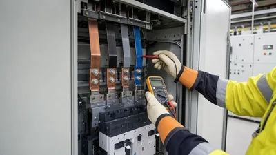
Checking three-phase voltage is a live measurement and falls under NFPA 70E. Use a voltmeter rated for the measurement category (CAT III for distribution panels, CAT IV at the service), test it on a known source before and after, and wear the PPE identified by the arc flash assessment.
- Verify the meter on a known live source.
- Measure line-to-line: A-B, B-C, C-A. All three should be close to nominal.
- Measure line-to-neutral: A-N, B-N, C-N, if a neutral exists.
- Measure neutral-to-ground at the panel; it should be near zero at the service bond.
- Measure each line to ground to detect an ungrounded system with a phase fault.
- Re-verify the meter on the known source.
| System | L-L expected | L-N expected | Notes |
|---|---|---|---|
| 208Y/120 V | 208 V | 120 V | All phases equal to neutral |
| 480Y/277 V | 480 V | 277 V | Common US industrial |
| 400/230 V | 400 V | 230 V | IEC low voltage |
| 240/120 V high-leg delta | 240 V | 120, 208, 120 V | B phase high leg, marked orange |
| 480 V delta, ungrounded | 480 V | None | L-G readings vary; equal if no fault |
Voltage unbalance calculation
NEMA MG 1 defines percent unbalance as 100 × (maximum deviation from average) / average. Readings of 478, 482 and 470 V average 476.7 V; the largest deviation is 6.7 V; unbalance is 100 × 6.7 / 476.7 ≈ 1.4%. Motor temperature rise grows roughly with twice the square of percent unbalance, so 1.4% adds about 4% heating; MG 1 calls for derating above 1% and advises against operation above 5%.
Phase Rotation Test: Using a Phase Sequence Indicator
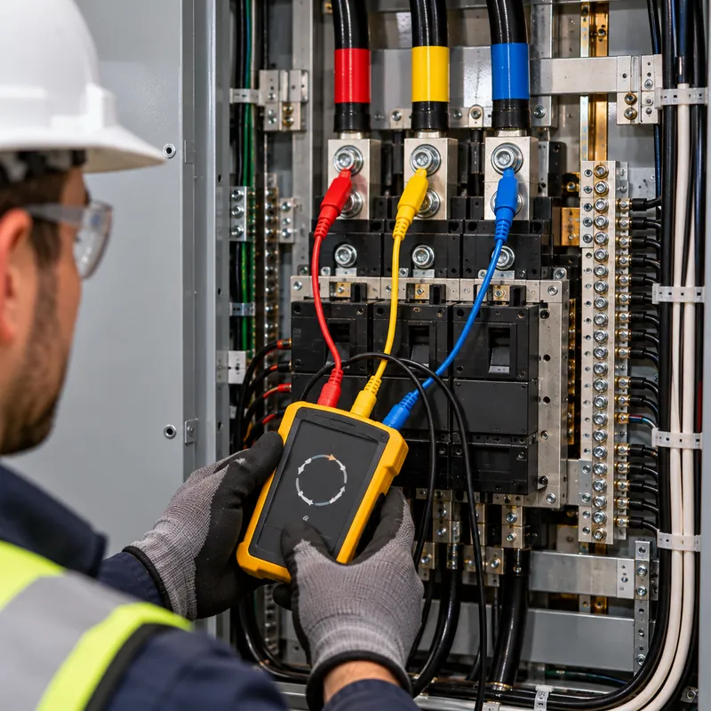
A phase sequence indicator (also called a phase rotation meter or phase sequence checker) is a test instrument that connects to the three lines and shows whether the sequence is L1-L2-L3 or reversed. Three types are common:
- Rotating disc type. A miniature induction motor turns a marked disc clockwise for positive sequence. Simple and intuitive, needs reasonable voltage.
- Static indicator type. An RC network lights one of two lamps or LEDs to indicate sequence; many also show presence of each phase.
- Non-contact type. Clips onto insulated conductors and senses the electric field, useful where terminals are shrouded.
Multifunction installation testers and power-quality analyzers also display sequence and phasor angles, which adds phase-angle confirmation on both sides of a transformer.
Checking phase rotation step by step
- Confirm the instrument's voltage rating and category for the system.
- Connect lead 1 to the conductor labelled A or L1, lead 2 to B or L2, lead 3 to C or L3.
- Read the indication; record positive (clockwise) or negative.
- Repeat at the other source or equipment terminals to compare.
- If reversed, isolate and swap two conductors at the agreed correction point, then retest.
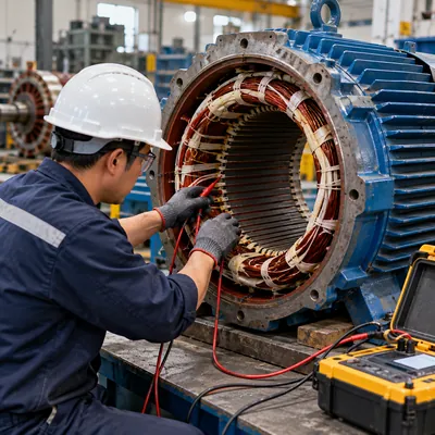
For motors, a complementary check is motor rotation testing with the motor uncoupled. Some three-phase rotation meters include a motor-side mode that indicates rotation from the residual voltage generated when the shaft is turned by hand, letting the motor be connected correctly before power is applied. Motor-side testing practices are described in the 3 phase motor testing guide.
Phase Sequence Through Transformers and Vector Groups
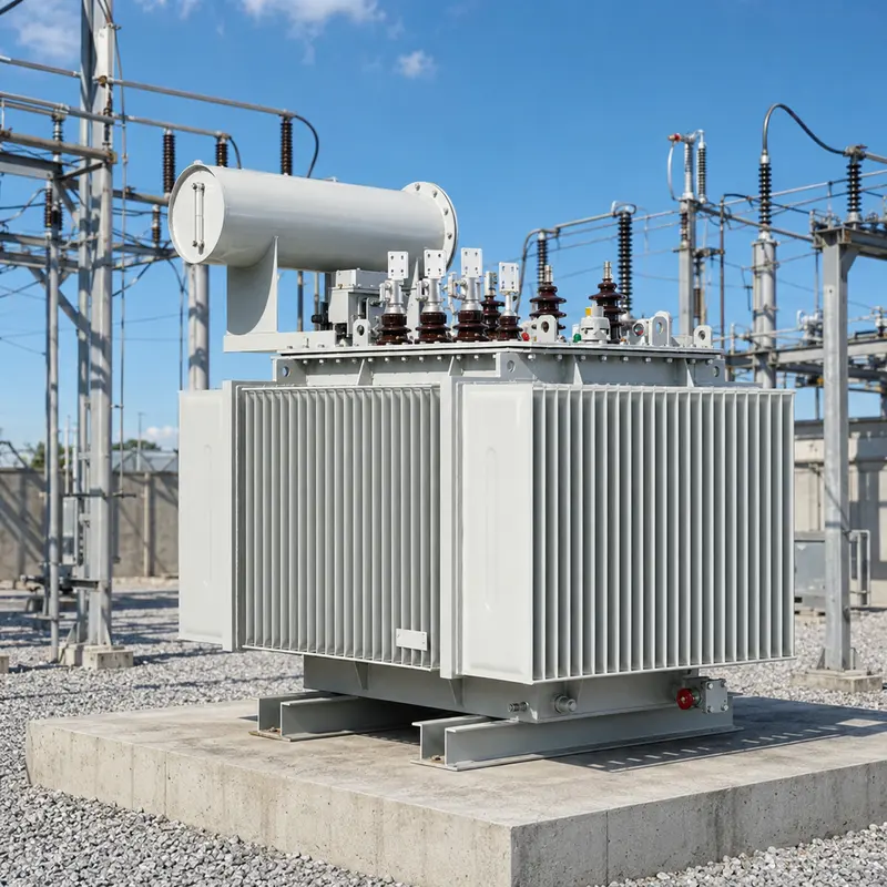
A three-phase transformer preserves phase sequence when its terminals are connected in standard order: H1-H2-H3 or 1U-1V-1W to A-B-C on the primary gives X1-X2-X3 or 2U-2V-2W in A-B-C order on the secondary. What changes is phase angle. A Dyn11 transformer's LV voltages lead the HV by 30°; a Dyn1 lags by 30°. IEEE C57.12.00 specifies the angular displacement for standard North American connections, and IEC 60076-1 defines the clock-number system used in vector groups.
Swapping two primary leads reverses sequence on both sides. It also changes the apparent vector group: a Dyn11 with two HV leads swapped behaves, for the reversed system, like a Dyn1. This matters when paralleling transformers or connecting to a ring with existing units. Vector group compatibility is discussed in transformer vector groups explained.
Phasing before paralleling
Rotation must match, but so must phase angle. The phasing check is done across the open tie point after confirming rotation:
- Measure voltage between A of source 1 and A of source 2, and repeat for B and C. Readings should be near zero.
- Measure A1 to B2: it should read full line voltage.
- Any significant voltage between like phases means wrong phasing, a different vector group, or a tap mismatch.
On MV systems the same check is done with phasing sticks or capacitive voltage indicators on the switchgear interfaces. These steps belong on the site acceptance test sheet, as described in the site acceptance test guide.
Commissioning a New Transformer: Rotation Checks to Record
When a new distribution transformer or compact substation is energized, rotation and phasing checks belong alongside insulation resistance, ratio and protection tests. A practical record includes:
- Primary sequence at the MV switchgear or ring main unit, by voltage indicator or phasing set.
- Secondary sequence at the LV main breaker line side.
- Secondary line-to-line, line-to-neutral and neutral-to-ground voltages at no load and with load.
- Tap position and measured secondary voltage at that position.
- Phasing to any existing source that may be paralleled, including generators and other transformers.
- Rotation of the first large motors, uncoupled where possible.
Factory tests confirm the internal connection. Every MARS transformer receives routine tests to IEC 60076-1 or IEEE C57.12.90, including ratio and phase displacement verification, so a site mismatch normally traces to external cabling or terminal labelling rather than the windings. Where a project involves several transformers, specifying identical vector groups and terminal markings removes the most common source of phasing errors.
Neutral-to-ground readings recorded at commissioning also serve as a baseline for later power-quality complaints, as discussed in the neutral to ground voltage guide. And for motor wiring choices that affect rotation and starting, see star and delta connections.
Next Steps: Specifying and Sourcing
Rotation and phasing problems are easiest to prevent at specification. In a transformer or substation RFQ, include:
- Vector group and angular displacement, matching any units that may run in parallel.
- Terminal marking standard (IEC 1U/1V/1W or IEEE H1/H2/H3 and X0-X3) and their physical order.
- Phase sequence of the supply network and the required sequence on the LV side.
- Cable entry positions and bushing arrangement relative to the switchgear to avoid crossed cables.
- Factory test list, including ratio and vector group verification, and whether FAT will be witnessed.
MARS manufactures oil-immersed transformers and compact transformer substations with clearly marked terminals and full routine test reports, for 50 and 60 Hz networks. Share your single-line diagram via the request a quote page to receive a matched offer.
Frequently asked questions
What is phase rotation?
Phase rotation is the order in which the three voltages of a three-phase system reach their peaks, normally A-B-C. It determines the direction of the rotating magnetic field in motors and must match between any sources that are paralleled. Reversing any two phase conductors reverses the rotation.
How do you check phase rotation?
Connect a phase sequence indicator to the three phase conductors in labelled order, L1, L2 and L3. The instrument shows clockwise or a positive-sequence lamp for correct rotation and counterclockwise or a negative-sequence lamp for reversed rotation. The test is a live measurement and must be done by a qualified person.
How do you test three phase power with a multimeter?
Measure the three line-to-line voltages, then each line-to-neutral voltage where a neutral exists. On 480Y/277 V, expect about 480 V between phases and 277 V to neutral. A multimeter cannot show phase sequence; that requires a rotation meter or power analyzer.
What happens if phase rotation is wrong?
Three-phase motors run backwards, which can damage compressors, reverse pumps and fans, and invert hoist controls. If two sources with different rotation are paralleled, closing the tie creates a phase-to-phase fault. Some drives, relays and meters also alarm on negative sequence.
Does a transformer change phase rotation?
No, with standard terminal connections a transformer keeps the same sequence on both sides but shifts the phase angle according to its vector group, for example 30° for Dyn1 or Dyn11. Swapping two primary leads reverses sequence on both windings.
How do I fix reversed phase rotation?
With the circuit isolated and locked out, swap any two phase conductors at an agreed point, usually at the load or at the new source, then retest. For a motor, swap two leads at the starter. For paralleled sources, correct the new source so its rotation and phasing match the existing system.
Written and reviewed by the MARS application engineering team in Shanghai, who specify and test transformers, switchgear, substations and battery storage for projects in 40+ countries. Last updated .
Tags: phase rotation phase sequence phase rotation test how to check 3 phase power three phase rotation meter