Key takeaways
- A transfer switch isolates the generator from the utility, preventing backfeed that can energize a de-energized line and endanger utility workers.
- A 30 A, 240 V inlet supports about 7.2 kW and a 50 A, 240 V inlet supports 12 kW, which sets the transfer switch rating for most portable generators.
- NEC 702.4 lets manual transfer equipment be sized for loads operated simultaneously, while automatic transfer must cover the full load unless load management is used.
- Portable generators with a bonded neutral need either a 3-pole switched-neutral transfer switch or a generator neutral unbonded per its instructions.
- Breaker interlock kits are a listed form of manual transfer only when used with the panel model they were evaluated for, under NEC 702.5.
Quick answer: A transfer switch is a double-throw device that connects a building's loads either to utility power or to a generator, never both, preventing dangerous backfeed onto utility lines. Types include manual circuit-selector switches, service-rated whole-house switches, breaker interlocks and automatic transfer switches. Size it to the generator output: a 12 kW, 240 V generator needs a 50 amp transfer switch.
Every generator that powers a building's fixed wiring needs a transfer switch. Without one, the generator can backfeed through the service and energize the utility transformer, which steps 240 V up to thousands of volts on lines crews believe are dead. The transfer switch is the single device that prevents this, while letting the owner choose which loads run during an outage.
This guide is for homeowners researching a home generator and transfer switch, contractors quoting residential and small commercial backup, and engineers who want the sizing logic in one place. It compares transfer switch types, works through a 50 amp generator sizing example, explains neutral switching and covers commercial generator connection points. For the operating sequence of automatic units, see our automatic transfer switch guide. Work on service equipment must follow local code and be done by a licensed electrician.
What Is a Transfer Switch and What Does It Look Like?
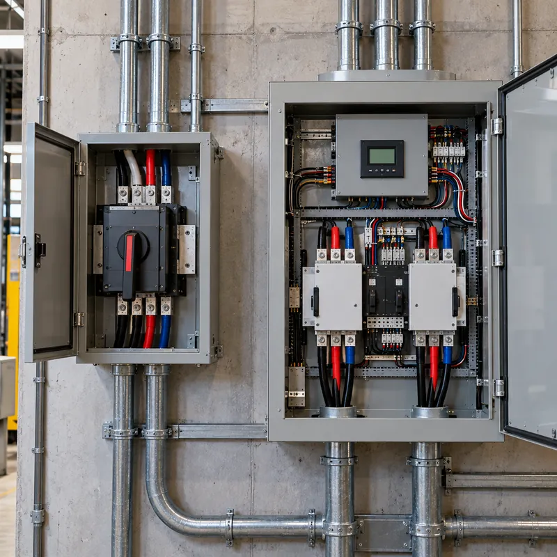
An electrical transfer switch is a switch with two input positions, normal (utility) and alternate (generator), and one output to the loads, arranged so the two sources can never be connected together. That break-before-make interlock is the whole point.
What a transfer switch looks like depends on its type:
- Circuit-selector manual switch: a small metal box mounted beside the main panel, with 6 to 10 rocker or toggle switches, each marked LINE, OFF and GEN, connected by a short flexible conduit to the panel and by cord to an outdoor power inlet box.
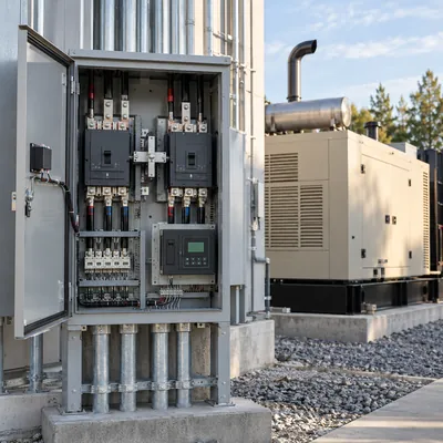
- Whole-house manual or automatic switch: a larger enclosure, often outdoors near the meter, containing a heavy double-throw mechanism or two interlocked breakers rated 100 to 400 A.
- Breaker interlock: no separate box at all; a sliding plate on the main panel cover that prevents the main breaker and a back-fed generator breaker from being on at the same time.
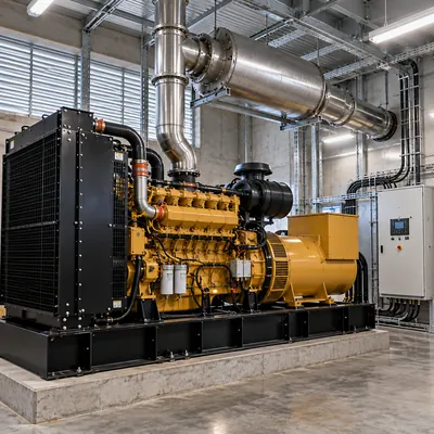
- Commercial transfer switch: a floor-standing cabinet with a motor-operated mechanism and controller, sometimes integrated as a section of the main switchboard.
A transfer box electrical installation also needs a power inlet: a weatherproof male receptacle, such as a NEMA L14-30 or 14-50 style inlet, that the generator cord plugs into. Never connect a generator through a dryer or range receptacle with a double-male cord; that arrangement has no interlock and can electrocute anyone touching the plug or working on the utility line.
Transfer Switch Types Compared
The right type depends on budget, how many circuits must run, and whether the generator starts automatically.
| Type | Typical rating | Operation | Loads covered | Best for |
|---|---|---|---|---|
| Manual circuit-selector | 30–50 A input, 6–10 circuits | Manual, per circuit | Selected circuits | Portable generator, essential loads |
| Breaker interlock kit | Up to generator breaker size | Manual, at the panel | Any circuit in panel, owner manages | Low-cost portable setup |
| Manual whole-house (service-rated) | 100–400 A | Manual handle | Entire service | Large portable or towable generator |
| Automatic transfer switch | 100–400 A residential, to 4,000 A commercial | Automatic with generator auto-start | Entire service or essential panel | Standby generators |
| Meter-socket transfer adapter | Up to service rating | Automatic or manual, at meter | Entire service | Retrofits where utility permits |
| Breaker-type transfer switch | Two interlocked breakers | Manual or motorized | Entire panel or switchboard | Commercial and industrial |
| AC transfer relay | 15–50 A | Automatic, built into equipment | Equipment output | Inverters, RVs, UPS bypass |
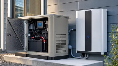
A breaker transfer switch, whether residential interlock or commercial two-breaker design, also provides overcurrent protection for the generator conductors. A double-throw switch without breakers relies on upstream protection. Meter-socket adapters require utility approval because they install at the utility's meter. For backup that switches without a generator, battery-based systems are compared in our home generator and battery guide.
How to Size a Transfer Switch for a Generator
Generator transfer switches are sized to the source that feeds them and to the loads they carry. Follow these steps:
- Find generator running output in watts at 240 V and convert to amps:
I = P / V. Use running watts, not surge watts. - Match the inlet and cord: 30 A for up to about 7.2 kW, 50 A for up to 12 kW. Larger towable units use single-pole cam-type connectors or hardwired connections.
- Choose the transfer switch rating equal to the inlet rating for circuit-selector types, or equal to the service rating for whole-house types.
- Check NEC 702.4 capacity: manual transfer equipment needs a generator able to carry the loads the owner will operate simultaneously; automatic transfer needs capacity for the full load transferred unless an energy management system limits it.
- Balance legs so neither 120 V leg exceeds half the generator rating.
- Confirm listings: UL 1008 for transfer switches, or a listed interlock evaluated for the specific panel.
| Generator running watts | Current at 240 V | Inlet and cord | Transfer switch |
|---|---|---|---|
| 3,600 W | 15 A | L14-20 style | 20–30 A, 120/240 V |
| 7,200 W | 30 A | L14-30 style | 30 A |
| 9,500 W | 40 A | 50 A, 14-50 or CS-type | 50 A |
| 12,000 W | 50 A | 50 A, 14-50 or CS-type | 50 A |
| 20,000 W+ | 83 A+ | Hardwired | 100–200 A whole house |
A 50 amp transfer switch for a portable generator is the most common residential choice because it can run a central air conditioner, well pump or electric water heater, which a 30 A system cannot. For converting other ratings, use our kW to amps guide.
Worked Example: Home Generator and Transfer Switch
A 120/240 V split-phase home needs backup for essential loads from a portable generator rated 7,500 W running, 9,500 W surge. The split-phase system is explained in our 240 V split-phase guide.
| Load | Voltage | Running current | Leg L1 | Leg L2 |
|---|---|---|---|---|
| Well pump, 1 hp | 240 V | 8 A | 8 A | 8 A |
| Refrigerator | 120 V | 6 A | 6 A | – |
| Lighting and receptacles | 120 V | 5 A | 5 A | – |
| Furnace blower | 120 V | 8 A | – | 8 A |
| Sump pump | 120 V | 8 A | – | 8 A |
| Total | 19 A | 24 A |
- Generator capacity per leg:
7,500 W / 240 V = 31 Aper leg on a balanced 240 V basis. - Running load: L2 at 24 A is the worst leg, leaving 7 A margin. Moving the refrigerator to L2 and the furnace to L1 would balance legs at 21 A and 22 A.
- Motor starting: the well pump draws roughly 5 to 6 times running current, about 45 A, for under a second. Starting it with other loads running consumes most of the surge capacity, so stagger motor starts.
- Selection: a 30 A, 6-circuit manual transfer switch with an L14-30 inlet carries these loads. If central air conditioning is added later, move to a 12 kW generator and 50 A switch.
A smart panel with load control can automate this priority logic, as covered in our smart electrical panel guide.
Switched vs Unswitched Neutral: 2-Pole or 3-Pole?
The neutral question causes more failed inspections and tripped GFCIs than any other transfer switch detail. NEC 250 allows only one neutral-to-ground bond in a system. The main panel already has one.
- Unswitched (solid) neutral, 2-pole switch. Only the hot conductors transfer; the generator neutral connects permanently to the building neutral. The generator is then not a separately derived system, and its own neutral-to-ground bond must be removed, otherwise neutral current divides between the neutral and the grounding conductor. Many portable generators ship bonded for stand-alone jobsite use, so this matters.
- Switched neutral, 3-pole switch. The neutral transfers with the hots, making the generator a separately derived system per NEC 250.30 that keeps its own bond. This suits bonded-neutral portable generators and generators with built-in GFCI outlets that would otherwise trip.
Signs of a wrong combination include generator GFCI receptacles tripping when connected to the house, current measured on the equipment grounding conductor, and measurable neutral-to-ground voltage at outlets; see our neutral-to-ground voltage guide. Follow the generator manufacturer's instructions; only a qualified person should change a generator's bonding configuration.
In three-phase commercial systems the same logic drives the choice between 3-pole and 4-pole ATS units, particularly where service ground-fault protection is installed.
Commercial Transfer Switches and Generator Connection Points
Commercial power transfer switch applications follow the same principles at larger scale, with a few additions:
- Generator docking stations: a manual transfer switch combined with a single-pole cam-type connection panel lets a rental generator be connected quickly during long outages or when the permanent generator is being serviced. NEC Article 700 requires provisions for connecting a temporary alternate source in certain emergency systems.
- Load bank connections: an extra set of terminals for testing generators under load without disturbing the building.
- Trapped-key or electrical interlocks between main breakers, tie breakers and generator breakers in double-ended switchboards.
- Coordination: transfer equipment must carry a withstand rating at the available fault current, and emergency systems require selective coordination.
Sizing a commercial transfer switch follows the formula I = S / (√3 × V). A 200 kVA generator at 208 V three-phase gives 200,000 / (1.732 × 208) = 555 A, so a 600 A transfer switch is selected; the same generator at 480 V gives 241 A and a 260 or 400 A frame depending on the manufacturer's range. For building-level design of the downstream panels, see our sub-panel guide and generator sizing guide.
Next Steps: Specifying and Sourcing Transfer Equipment
For residential projects, decide first between essential-circuit and whole-house backup, then size the generator, inlet and transfer switch together using the table above. Confirm UL 1008 listing, neutral switching to suit the generator, and an outdoor emergency disconnect where the adopted NEC requires one. A licensed electrician should install and the authority having jurisdiction should inspect. Keep the generator manual, the transfer switch wiring diagram and the circuit list together near the switch so anyone operating it during an outage follows the correct sequence.
For commercial, industrial and utility projects, include in the RFQ:
- Voltage, phases, frequency and available fault current.
- Transfer switch current, pole count and transition type.
- Manual, automatic or bypass-isolation construction.
- Generator connection provisions: docking station, load bank terminals.
- Integration into the switchboard or separate enclosure, with enclosure rating.
MARS does not sell residential transfer switches or generators. We build low-voltage switchboards that integrate transfer switching equipment, motor-operated breaker transfer pairs and generator connection sections to IEC 61439, plus MV switchgear for utility-level changeover, with typical lead times of 25 to 45 days. See our HV and LV switchgear and send your single-line diagram via the quote form.
Frequently asked questions
Do I need a transfer switch for a portable generator?
Yes, whenever the generator powers circuits in the building's fixed wiring. A transfer switch or listed interlock prevents backfeed onto utility lines, which is required by NEC 702 and protects utility workers. Plugging appliances directly into the generator with extension cords does not require a transfer switch.
What size transfer switch do I need for a 50 amp generator?
A generator with a 50 A, 240 V outlet delivers up to 12 kW, so use a 50 amp transfer switch with a matching 50 A power inlet and cord. Choose the circuit count to suit the essential loads, or a service-rated whole-house switch with load management for full coverage.
What is the difference between a transfer switch and an interlock kit?
A transfer switch is a separate listed device with its own double-throw mechanism. An interlock kit is a mechanical plate that prevents the main breaker and a generator breaker from being on together in the existing panel. Interlocks cost less but must be listed for that specific panel model.
Is a manual or automatic transfer switch better?
Automatic transfer switches suit permanently installed standby generators with auto-start, restoring power within seconds without anyone present. Manual switches suit portable generators that must be started by hand, and cost much less. The generator's starting method usually decides the choice.
Can a transfer switch power the whole house?
Yes. A service-rated whole-house transfer switch transfers the entire service, typically 100 to 400 A. The generator must then carry the full load, unless load management sheds large appliances, as allowed by NEC 702.4 for automatic transfer. Manual whole-house switches rely on the owner limiting loads.
Does a transfer switch need to switch the neutral?
It depends on the generator. If the generator's neutral is bonded to its frame, use a 3-pole switched-neutral transfer switch so the generator is a separately derived system. If the neutral is unbonded, a 2-pole switch with solid neutral is normal. Follow the generator instructions.
Written and reviewed by the MARS application engineering team in Shanghai, who specify and test transformers, switchgear, substations and battery storage for projects in 40+ countries. Last updated .
Tags: transfer switch generator transfer switches 50 amp transfer switch home generator and transfer switch residential transfer switch