Key takeaways
- An ATS combines a power switching mechanism, a controller with voltage and frequency sensing, and engine-start contacts that command the generator to run.
- NEC 700 emergency systems and NFPA 110 Level 1, Type 10 systems must restore power within 10 seconds of normal source failure.
- Closed-transition ATS units parallel both sources for typically less than 100 milliseconds, giving a break-free retransfer when utility power returns.
- UL 1008 withstand and closing ratings must equal or exceed the available fault current, and are tied to a specific upstream breaker or a time duration.
- A 500 kW, 0.8 PF standby load at 480 V draws I = 625,000 / (1.732 × 480) = 752 A, so an 800 A automatic transfer switch is selected.
Quick answer: An automatic transfer switch (ATS) is a device that monitors the normal power source and, when voltage or frequency fails, signals a standby generator to start and transfers the load to it once the generator is stable. When utility power returns, it retransfers the load and lets the generator cool down. ATS equipment is listed to UL 1008 or built to IEC 60947-6-1.
A standby generator is only as useful as the switch that connects it. The automatic transfer switch decides when the utility has failed, starts the engine, chooses the moment to transfer, protects the generator from being connected out of phase, and puts everything back when the grid returns, without anyone in the building touching a handle.
This guide is for facility engineers, consulting engineers and contractors specifying an ATS for commercial, industrial, healthcare or data-center standby systems. It explains the operating sequence and timers, compares transition types, covers UL 1008 and IEC ratings, and works through a sizing example. Residential whole-house applications are covered briefly, and our companion transfer switch types and sizing guide covers manual switches and portable generators in more depth.
What Is an Automatic Transfer Switch (ATS)?
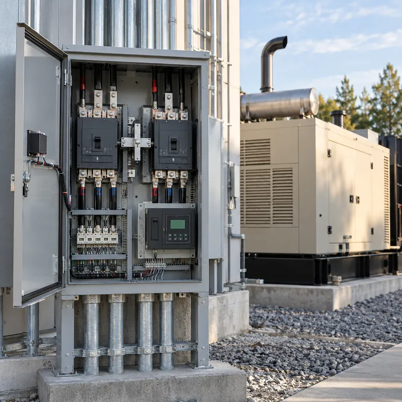
In electrical terms, ATS means automatic transfer switch: a self-acting switch that transfers one or more load conductors from one power source to another without operator intervention. IEC documents call the same device an ATSE (automatic transfer switching equipment), and in some markets it is sold as a dual power automatic transfer switch or ATS changeover switch.
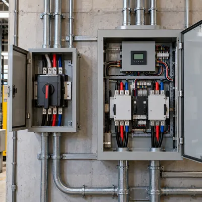
Every ATS electrical system has three functional parts:
- Power switching mechanism. Either a contactor-type mechanism (a double-throw, mechanically interlocked switch) or a breaker-type mechanism using two motor-operated circuit breakers with interlocking. IEC 60947-6-1 calls these Class PC (switch-based, not intended to interrupt short circuits) and Class CB (breaker-based, with integral overcurrent protection).
- Controller. A microprocessor that senses voltage, frequency and often phase rotation on both sources, runs the timing sequence, and records events.
- Engine-start circuit. A dry contact that closes or opens to start the generator, plus exerciser logic for weekly or monthly test runs.
An automatic changeover switch in a building with two utility feeds or a utility plus a battery system works in the same way; only the start signal changes. On drawings the ATS appears as a double-throw symbol, explained in our switch and relay symbols guide.
How Does an Automatic Transfer Switch Work?
The standby generator operation with an automatic transfer switch follows a fixed sequence, with adjustable timers that suit the load and the utility.
- Detect failure. The controller sees normal-source voltage fall below the dropout setting, typically 80 to 85 percent of nominal, or frequency move out of tolerance.
- Engine start delay. A short delay rides through momentary dips and reclosing operations on the utility feeder.
- Start the generator. The engine-start contact signals the genset controller to crank.
- Confirm emergency source. The ATS waits until generator voltage and frequency reach about 90 percent of nominal.
- Transfer. The mechanism opens the normal contacts and closes the emergency contacts, with optional center-off delay for motor loads.
- Retransfer delay. After the utility returns, the ATS waits to make sure it is stable before switching back.
- Engine cooldown. The generator runs unloaded for several minutes, then stops.
| Timer | Purpose | Typical setting |
|---|---|---|
| Engine start delay | Ride through momentary outages | 1–3 s |
| Normal-to-emergency delay | Allow generator stabilization, stagger loads | 0–5 s (emergency loads 0 s) |
| Center-off (neutral) delay | Let motor residual voltage decay | 0.5–3 s |
| Emergency-to-normal delay | Confirm utility stability | 5–30 min |
| Engine cooldown | Cool turbocharger and engine | 3–5 min |
Emergency systems under NEC Article 700 must transfer within 10 seconds; legally required standby under Article 701 within 60 seconds; optional standby under Article 702 has no time requirement. For generator sizing against these loads, see our generator sizing guide.
Types of Automatic Transfer Switch: Transition Methods
The transition method determines what the load sees during transfer. Choose it by load sensitivity and utility rules.
| Type | How it transfers | Load interruption | Typical use |
|---|---|---|---|
| Open transition | Break-before-make, direct | About 50–150 ms on transfer | General standby, lighting, small motors |
| Delayed transition | Break-before-make with timed center-off | 0.5–3 s, adjustable | Large motors, VFDs, transformers |
| In-phase monitor | Open transition when sources are near synchronism | Brief, phase-matched | Motor loads without center-off |
| Closed transition | Make-before-break, sources paralleled briefly | None on retransfer and testing | Hospitals, data centers, process plants |
| Soft-load closed transition | Generator paralleled and ramped | None | Peak shaving, utility-sensitive sites |
Open transition is always used when the normal source has failed, because there is nothing to parallel with. Closed transition only avoids the second outage during retransfer and during test runs, which is valuable where every interruption reboots IT equipment or trips process lines. Utilities typically restrict closed-transition overlap to under about 100 ms and may require protective relaying.
Construction options add further types:
- Bypass-isolation ATS: a manual bypass switch keeps the load fed while the ATS mechanism is withdrawn for maintenance. Common in healthcare and data centers; see our data center power distribution guide.
- Service-entrance-rated ATS: includes the service disconnect and overcurrent protection on the utility side, so it can be installed directly after the meter.
Standards and Ratings: UL 1008, IEC 60947-6-1 and NFPA 110
In North America, transfer switches must be listed to UL 1008 for use in emergency and standby systems. Internationally, IEC 60947-6-1 covers transfer switching equipment. Installation and performance requirements come from the NEC and NFPA 110.
- NEC Article 700 (emergency): life-safety loads such as egress lighting and fire pumps; transfer in 10 s; dedicated ATS; selective coordination required.
- NEC Article 701 (legally required standby): loads such as smoke control and ventilation; transfer within 60 s.
- NEC Article 702 (optional standby): business continuity; no time limit.
- NFPA 110 classifies emergency power supply systems by Level (1 where failure could cause loss of life), Type (maximum seconds to restore power, Type 10 = 10 s) and Class (minimum run time in hours).
- IEC 60947-6-1 utilization categories: AC-31 for non-inductive loads, AC-32 for mixed resistive and inductive loads, AC-33 for motor loads and AC-35 and AC-36 for discharge and incandescent lamps.
The rating most often missed is the withstand and closing rating (WCR). UL 1008 tests that the ATS can carry and close onto a fault until the upstream device clears it. Ratings are published for use with specific breakers, with any breaker for a short time (for example, 3 cycles), or for longer durations such as 30 cycles that allow short-time-delay breakers upstream for selective coordination. The ATS WCR must be at least the available fault current at its terminals, calculated as shown in our fault current calculation guide.
Sizing an Industrial ATS: Worked Example
An industrial automatic transfer switch is sized on continuous current, fault withstand and pole count.
Given: a 480Y/277 V plant with a 500 kW, 0.8 PF standby generator feeding critical process loads. Available fault current from the utility transformer at the ATS location is 42 kA. Upstream utility-side protection is an electronic-trip air circuit breaker with short-time delay for selectivity.
- Generator kVA:
S = 500 / 0.8 = 625 kVA. - Rated current:
I = S / (√3 × V) = 625,000 / (1.732 × 480) = 752 A. - Select the next standard frame: 800 A. If the load is largely motors, confirm the AC-33 or UL 1008 motor-load rating.
- Fault rating: require WCR of at least 42 kA. Because the upstream ACB uses short-time delay, specify a time-based rating (for example, 30 cycles) rather than a specific-breaker rating that assumes instantaneous clearing.
- Pole count: if the service has ground-fault protection, which NEC 230.95 requires on solidly grounded wye services of 1,000 A or more above 150 V to ground, and the generator is a separately derived system, choose a 4-pole switched-neutral ATS to avoid nuisance tripping from neutral current returning through two bonding points.
- Transition: process motors favor a delayed-transition or in-phase monitor; IT loads favor closed transition.
For the generator breaker and feeder breakers around the ATS, use our industrial circuit breaker selection guide.
Home Automatic Transfer Switch for Whole House Generators
A home automatic transfer switch for a whole house generator works on the same principles at 120/240 V single-phase, usually in 100, 200 or 400 A sizes. Two configurations dominate:
- Service-rated whole-house ATS installed between the meter and the main panel, transferring the entire service. Paired with load-management modules that shed air conditioners or ranges so a smaller generator can carry the home.
- Essential-load ATS feeding a separate critical-loads panel, with only selected circuits backed up.
An automatic transfer switch for a portable generator is possible only when the generator has an electric start and a two-wire auto-start input. Most portable sets must be started by hand, so a manual transfer switch or interlock is the normal solution, as described in our transfer switch sizing guide. A battery system can replace or supplement the generator; our hybrid generator and battery systems guide explains how.
Residential points that matter:
- The ATS must be listed to UL 1008 and suitable as service equipment if installed ahead of the main panel.
- NEC 702.4 requires the generator to carry the full load the ATS transfers, unless a load management system limits it.
- The 2020 and later NEC require an outdoor emergency disconnect for one- and two-family dwellings, which some service-rated ATS units provide.
Work on service equipment must follow local code and be done by a licensed electrician.
Next Steps: Specifying and Sourcing an ATS
A complete ATS specification includes:
- System voltage, phases, wires and frequency.
- Continuous current rating and load type (AC-31, AC-32 or AC-33 in IEC terms; motor, resistive or mixed in UL terms).
- WCR at the available fault current, with the upstream protective device type and clearing time.
- Transition type: open, delayed, in-phase, closed or soft-load.
- Pole count: 3-pole or 4-pole switched neutral.
- Options: bypass-isolation, service-entrance rating, communication (Modbus TCP), metering and exerciser.
- Applicable articles: NEC 700, 701 or 702, NFPA 110 Level and Type.
MARS integrates automatic transfer switching into its low-voltage switchboards, using ATSE or motor-operated breaker pairs in GGD, GCS and MNS assemblies to IEC 61439 and IEC 60947-6-1, and builds medium-voltage auto-changeover schemes with KYN28 metal-clad switchgear and ring main units. These suit generator, dual-utility and BESS backup schemes with a battery energy storage system. Typical lead time is 25 to 45 days. For larger backup design questions, read our commercial backup power system design guide, then review HV and LV switchgear and send your single-line diagram via the quote form.
Frequently asked questions
What does an automatic transfer switch do?
An automatic transfer switch monitors utility power and, when it fails, starts the standby generator and transfers the load once generator voltage and frequency are stable. When utility power returns and stays stable, it retransfers the load back and lets the generator run unloaded to cool down before stopping.
How long does an ATS take to transfer?
Typical total time from outage to generator power is 5 to 15 seconds, set by engine start delay, cranking and stabilization. Emergency systems under NEC Article 700 and NFPA 110 Type 10 must restore power within 10 seconds. The switching mechanism itself operates in a fraction of a second.
What is the difference between open and closed transition ATS?
An open transition ATS disconnects one source before connecting the other, so the load sees a brief interruption. A closed transition ATS briefly parallels both sources, usually for less than 100 milliseconds, giving a break-free retransfer to utility power and break-free generator testing.
Can you use an automatic transfer switch with a portable generator?
Only if the portable generator has electric start and a two-wire auto-start input that the ATS can command. Most portable generators need manual starting, so a manual transfer switch or listed interlock kit is the usual, lower-cost solution for portable units.
What size automatic transfer switch do I need?
Size the ATS for the full current of the source or load it transfers. For three-phase, use I = kVA × 1,000 / (1.732 × V). A 625 kVA generator at 480 V gives 752 A, so an 800 A ATS is selected, with a WCR at least equal to the available fault current.
When do you need a 4-pole automatic transfer switch?
A 4-pole switched-neutral ATS is used when the generator is a separately derived system with its own neutral-to-ground bond, most often where ground-fault protection is installed on the service. Switching the neutral prevents neutral current from flowing through two bonds and causing nuisance ground-fault trips.
Written and reviewed by the MARS application engineering team in Shanghai, who specify and test transformers, switchgear, substations and battery storage for projects in 40+ countries. Last updated .
Tags: automatic transfer switch automatic transfer switch for generator generator ats ats electrical types of automatic transfer switch