Key takeaways
- Relay coils are circles in NEMA ladder diagrams and rectangles with terminals A1 and A2 in IEC 60617 drawings, and contacts carry the same tag as the coil.
- Contact terminal numbers per IEC 60947-5-1 use a second digit of 1-2 for normally closed and 3-4 for normally open, so 13-14 is the first NO contact.
- NEMA process switches share one blade shape and differ by actuator: a roller or wedge for limit, a semicircle diaphragm for pressure and a float for level.
- A three-way lighting circuit uses two SPDT switches joined by two traveler conductors, and each four-way switch added between them is a DPDT crossover.
- A 24 V DC relay coil rated 1.2 W draws I = P / V = 50 mA, well within a typical 0.5 A transistor PLC output.
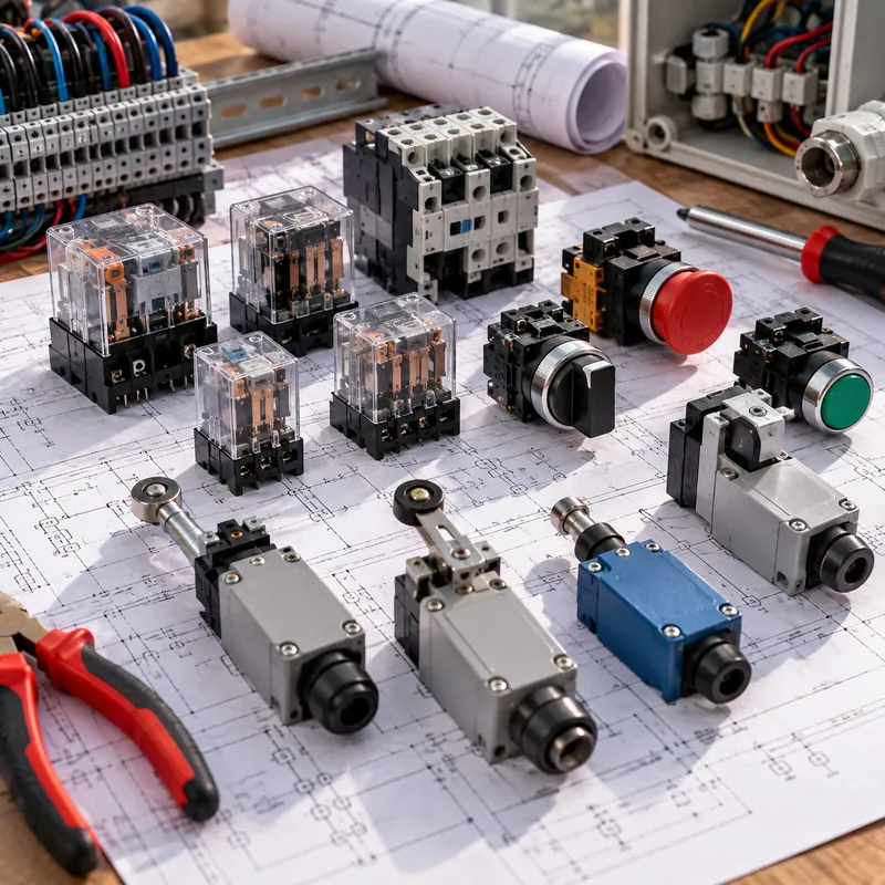
Quick answer: A relay symbol has two parts: the coil, drawn as a circle labeled CR in NEMA ladder diagrams or a rectangle labeled -K1 with terminals A1-A2 in IEC drawings, and its contacts, drawn as normally open or normally closed switch elements elsewhere on the drawing. Switch symbols add an actuator mark showing what operates them: a pushbutton, selector, cam, pressure, temperature or level.
Control circuits are built from switches and relays. Whether it is a pump started by a float, a conveyor stopped by a limit switch or a breaker tripped through an auxiliary relay, the logic on the drawing is expressed entirely in contact and coil symbols. Reading those symbols quickly is the core skill of anyone who commissions or troubleshoots control panels.
This guide is for controls engineers, panel builders, maintenance electricians and technicians. It explains how switch and relay symbols are constructed in NEMA ladder practice and IEC 60617, the meaning of poles, throws and contact states, process-sensing switch symbols, transducers, and the residential three-way and four-way switch symbols that confuse many readers.
How Are Switch Symbols Built? Poles, Throws and Contact States
A switch is a device that opens or closes one or more circuits by moving contacts. Every switch symbol combines three pieces of information: the number of poles (independent circuits switched together), the number of throws (positions each pole can connect to) and the normal state of the contacts.
| Type | How the symbol is drawn | Typical use |
|---|---|---|
| SPST (single-pole single-throw) | One hinged blade angled away from one fixed contact | Simple on/off |
| SPDT (single-pole double-throw) | One blade pivoting between two fixed contacts | Changeover, selector, 3-way lighting |
| DPST (double-pole single-throw) | Two SPST blades joined by a dashed line | Switching both conductors of a 240 V load |
| DPDT (double-pole double-throw) | Two SPDT blades joined by a dashed line | Polarity reversal, 4-way lighting |
| Slide switch | Usually drawn as SPDT; sometimes a bar bridging two of three contacts | Electronics, mode selection |
| Rotary switch | A pivoting wiper with several fixed contacts arranged on an arc | Multi-position selection |
Normal state
Schematics show contacts in their shelf state: device not operated and coil de-energized. A normally open (NO) contact is open in that state; a normally closed (NC) contact is closed. A closed switch symbol, with the blade resting on its contact, therefore signals an NC device, not a switch that happens to be on. Some ladder drawings add notes like “held closed” for limit switches that are operated when the machine is at rest.
For the wider family of diagram symbols, see the electrical symbols chart; for protective switching devices such as breakers and disconnectors, see the circuit breaker and fuse symbols guide.
Relay Symbol: Coil, Contacts and Terminal Numbers
A relay is an electrically operated switch: current in a coil moves an armature that opens or closes contacts in separate circuits. The schematic symbol for a relay is split so that the coil can sit in one rung and its contacts wherever they act.
| Element | NEMA / JIC ladder | IEC 60617 |
|---|---|---|
| Control relay coil | Circle labeled CR1, CR2 | Rectangle labeled -K1, terminals A1 (+) and A2 (−) |
| Contactor coil | Circle labeled M | Rectangle labeled -KM1 or -Q1 |
| NO contact | Two short parallel vertical lines | Open blade, terminals x3-x4 |
| NC contact | Parallel lines crossed by a diagonal | Blade on contact, terminals x1-x2 |
| Changeover (SPDT) contact | NO and NC pair sharing a common | Blade between two contacts, terminals 11-12-14 |
| Time delay contacts | Contact with an arc (parachute) showing on-delay or off-delay action | Coil rectangle with timing qualifier, contacts with timing arc |
| Solid-state (electronic) relay | Rectangle with input LED and output switching element | Rectangle with semiconductor qualifier |
IEC 60947-5-1 terminal numbering makes wiring diagrams readable: the first digit is the contact position (1, 2, 3...), the second digit is the function, 1-2 for NC and 3-4 for NO, with 5-6 and 7-8 for special functions such as timers and overload contacts. So 13-14 is the first NO contact, 21-22 the second, an NC.
A simple relay symbol on a PCB schematic often shows coil and contacts together inside a dashed box, labeled SPST, SPDT or DPDT according to the contact set. A DPDT relay symbol shows two changeover contacts linked by a dashed line to one coil. Protection relays use different conventions, explained in the protective relay selection guide.
Pushbutton, Selector Switch and Universal On/Off Symbols
Manually operated control devices are distinguished by their actuator.
- Push button circuit symbol (NEMA): a horizontal bar on a short stem above two contact points. For an NO button the bar sits above the contacts without touching; for an NC button the bar rests across them from below. A mushroom-head emergency stop adds a semicircular cap to the stem.
- Push switch (IEC): a switch blade with a dashed operating line ending in a push-operator qualifier, a small bracket shape. Latching (push-push) types add a detent mark.
- Symbol of selector switch (NEMA): contacts drawn with a position chart beside them; an X in a column means that contact is closed in that position (for example HAND, OFF, AUTO).
- Selector switch (IEC): a blade with a turn-operator qualifier on the dashed line, with a separate contact diagram listing positions.
- Key switch: as selector, with a key qualifier.
Universal on/off symbols
Equipment panels use IEC 60417 marking symbols rather than schematic symbols:
| Mark | Meaning | IEC 60417 ref. |
|---|---|---|
| Vertical line ( I ) | On (power) | 5007 |
| Circle ( O ) | Off (power) | 5008 |
| Broken circle with line through the gap | Standby | 5009 |
| Line inside a circle | Push-on/push-off | 5010 |
These markings appear on nameplates and panel doors; on a drawing the same device is still drawn as a switch or pushbutton symbol.
Limit, Pressure, Temperature and Level Switch Symbols
Process and position switches use the basic contact symbol with an actuator showing what operates it. In NEMA ladder practice, the NO version has the blade below the fixed contact and the NC version has it above, with the actuator attached to the blade.
| Switch | NEMA actuator drawn on the blade | IEC qualifier |
|---|---|---|
| Limit switch | Small wedge or roller (triangle or circle) on the blade end | Position-operated qualifier, roller or cam on dashed line |
| Pressure or vacuum switch | Semicircle (diaphragm) on a stem below the blade | Box with letter p on the operating line |
| Temperature switch | Stem ending in a sensing bulb or wavy element | Box with θ (theta) |
| Liquid level switch | Circle (float) on a stem | Box with level or float qualifier |
| Flow switch | Flag or paddle on a stem | Box with flow qualifier |
| Foot switch | Bar with foot-pedal shape | Foot-operator qualifier |
A limit switch electrical symbol labeled LS1 and drawn NC held open, for example, means the contact is normally closed but is held open by the machine in its rest position. The pressure switch schematic symbol is usually tagged with setpoint and differential, for example PS1 open at 6 bar, reset 5 bar.
In transformers and switchgear these switches are everywhere: oil temperature and winding temperature switches, pressure relief devices, gas (Buchholz) relays and SF6 density monitors all appear as contact symbols on the control schematic. Our winding temperature guide shows how alarm and trip contacts are staged.
Pressure Transducer and Current Transducer Symbols
A transducer is a device that converts a physical quantity into a proportional electrical signal, rather than a simple on/off contact. Transducers therefore use different symbols from switches.
- Pressure transducer symbol: on instrumentation drawings per ISA 5.1, a circle (instrument bubble) containing the tag letters PT, with a loop number. On electrical schematics it is a rectangle labeled with p and the output signal, for example
0-10 bar / 4-20 mA, with supply and signal terminals. - Current transducer symbol: a current transformer or Hall-effect sensor around the conductor, drawn as a circle or ring on the line, connected to a rectangle showing the output, for example
0-400 A / 4-20 mA. ISA tags it IT or CT depending on project. - Current transformer (instrument CT): a small circle or coil on the primary line with polarity dots, ratio noted, such as 400/5 A.
A transmitter on instrument loop drawings is drawn the same way as a transducer bubble, with the letter T in its tag. Its 4-20 mA output then feeds a PLC analog input, which may in turn energize relays, closing the loop between analog sensing and contact logic.
The difference between a current transformer and an electronic current transducer matters for burden, accuracy and isolation. The current transformer working principle guide covers the physics, and polarity and ratio marks are explained in our guide on how to read electrical drawings.
3 Way Switch Symbol and Four-Way Lighting Circuits
The three way switch symbol appears in two forms. On a floor plan it is the letter S3; on a schematic it is an SPDT switch with a common terminal and two traveler terminals.
- The line (hot) conductor goes to the common terminal of the first three-way switch.
- Two traveler conductors connect the traveler terminals of the first switch to those of the second.
- The common terminal of the second switch feeds the luminaire, and the neutral goes directly to the luminaire.
- For each additional control point, a four-way switch (a DPDT wired as a crossover) is inserted in the travelers, either passing them straight through or swapping them.
Flipping either switch changes whether the two commons are connected through a traveler, so the light toggles from any location. Under NEC 404.2(C), most switch locations controlling lighting loads in new work need a grounded (neutral) conductor available, which affects how the cables between switches are chosen.
In UK and IEC terminology the same SPDT device is called a two-way switch, and the crossover is called an intermediate switch. That naming difference is a common source of confusion when reading imported drawings. Residential switch work must follow local code and be carried out by a licensed electrician. For full layouts, see the electrical wiring diagram guide.
Worked Example: Checking Relay Coil and Contact Ratings
Symbols tell you what a relay does; the ratings tell you whether it will survive. A typical check when a PLC output drives an interposing relay that switches a solenoid valve:
Coil side
Relay coil: 24 V DC, 1.2 W.
I = P / V = 1.2 W / 24 V = 0.05 A = 50 mA
A transistor PLC output rated 0.5 A per point handles this easily. A flyback diode across the coil (drawn as a diode symbol in parallel with the coil, cathode to A1 +) suppresses the turn-off voltage spike.
Contact side
Solenoid valve: 230 V AC, 15 VA holding, 45 VA inrush. Relay contact rating: AC-15 utilization category per IEC 60947-5-1, 3 A at 230 V.
Contact capacity = 230 V × 3 A = 690 VA and inrush current = 45 VA / 230 V ≈ 0.2 A
The contact is comfortably rated. The same check for a contactor coil as the load uses the contactor's sealed and inrush VA from its data sheet; NEMA pilot duty ratings such as A600 or B300 provide equivalent values in North America.
These checks belong on the control schematic or the device schedule, so that anyone replacing a relay later uses one of the same rating. Panel design practice is covered in the electrical control panel guide, and motor contactor circuits in the motor control symbols guide.
Next Steps: Specifying Control and Protection Wiring for Switchgear
When you order switchgear or a substation, the control schematics are part of the deliverable. To get drawings you can maintain:
- Specify the symbol standard (IEC 60617 or NEMA/IEEE) and device tagging convention (IEC 81346 or project-specific).
- Define auxiliary voltage (for example 110 V DC or 220 V DC trip supply) and relay coil voltages.
- List the alarm and trip contacts needed from transformer protection devices and switchgear, with NO/NC state and terminal numbers.
- Request terminal block schedules and cross-referenced wiring diagrams in addition to schematics.
- Ask for interlock logic to be shown explicitly with contact symbols, not just described in text.
MARS supplies KYN28 metal-clad switchgear, SF6 ring main units and IEC 61439 LV boards with complete schematics and wiring diagrams, and every unit receives routine tests before shipment, including functional checks of control circuits. See the HV and LV switchgear range, and send your requirements through the quote request form.
Frequently asked questions
What is the electrical symbol for a relay?
A relay is drawn as a coil plus contacts. In NEMA ladder diagrams the coil is a circle labeled CR, and contacts are two parallel lines, with a diagonal for normally closed. In IEC 60617 drawings the coil is a rectangle labeled -K1 with terminals A1 and A2, and contacts are switch blades numbered 13-14 or 21-22.
What is the difference between an SPST and SPDT relay symbol?
An SPST relay symbol shows one coil and one contact that is either open or closed, with two terminals. An SPDT relay symbol shows one coil and a changeover contact with three terminals: a common, a normally closed and a normally open, numbered 11, 12 and 14 in IEC practice. A DPDT relay has two changeover contacts.
What does the limit switch symbol look like?
In NEMA ladder practice a limit switch is a switch blade with a small wedge or roller attached to it. The normally open version has the blade below the fixed contact, the normally closed version above it. IEC drawings show a switch blade with a roller or cam operator on the dashed operating line and the tag -B or -S.
What is the pressure switch electrical symbol?
A NEMA pressure switch symbol is a switch blade operated by a semicircle on a stem, representing a diaphragm. The semicircle sits beneath the blade, and the contact can be shown normally open or normally closed. IEC drawings show a switch with a box on the operating line containing the letter p, plus the setpoint.
What does a 3 way switch symbol mean?
On a floor plan, S3 marks a three-way switch, one of a pair that controls the same lights from two locations. On a schematic, a three-way switch is drawn as an SPDT switch with one common and two traveler terminals. In UK and IEC terminology the same device is called a two-way switch.
How do you read contact numbers like 13-14 and 21-22?
Under IEC 60947-5-1, the first digit is the contact position on the device and the second is its function. Second digits 1 and 2 indicate a normally closed contact, and 3 and 4 indicate normally open. So 13-14 is the first contact and is NO, while 21-22 is the second contact and is NC. Digits 5-6 and 7-8 mark special contacts.
Written and reviewed by the MARS application engineering team in Shanghai, who specify and test transformers, switchgear, substations and battery storage for projects in 40+ countries. Last updated .
Tags: relay symbol switch symbols limit switch symbol pressure switch symbol 3 way switch symbol