Key takeaways
- Three-phase voltage consists of three alternating currents of identical frequency and amplitude, displaced from each other by an electrical phase angle of 120 degrees.
- In a balanced wye or star system, the line-to-line voltage is exactly equal to the line-to-neutral phase voltage multiplied by the square root of three (approximately 1.732).
- European three-phase low-voltage distribution is standardised under IEC 60038 at 400 V line-to-line and 230 V line-to-neutral at a nominal frequency of 50 Hz.
- North American industrial facilities primarily use 480 V line-to-line (277 V line-to-neutral) or 208 V line-to-line (120 V line-to-neutral) at 60 Hz.
- Total balanced three-phase active power in watts is calculated using the formula P equals the square root of three multiplied by line voltage, line current, and the load power factor.
Quick answer: A 3 phase voltage supply delivers three distinct sinusoidal alternating voltages that operate at the same frequency and magnitude but are electrically separated by an angular phase displacement of 120 degrees (2π/3 radians). This polyphase configuration allows commercial and industrial systems to transmit 73 percent more power than single-phase circuits using fewer conductor materials.
Alternating current (AC) distribution networks globally rely on three-phase infrastructure for generation, transmission, and heavy industrial consumption. By displacing three alternating voltage waveforms symmetrically around a central cycle, a three-phase system delivers continuous, smooth instantaneous power rather than the pulsating power characteristic of single-phase circuits. Understanding the exact electrical behavior of these systems is fundamental when sizing distribution equipment, configuring medium-voltage substations, or procuring plant machinery. For an overarching engineering assessment of transformer technologies that step down or isolate these supplies, consult our comprehensive 3 phase transformer guide.
How Many Volts in Three Phase Power Systems?
The number of volts in a three-phase power system depends directly on whether the potential difference is measured line-to-line or line-to-neutral, as well as the regional utility grid standard. When engineers ask how many volts in three phase networks, they typically refer to nominal low-voltage (LV) or medium-voltage (MV) distribution ratings, which are governed by jurisdictional standards such as IEC 60038 or ANSI C84.1.
In polyphase networks, two distinct potential measurements exist across the circuit conductors:
- Line-to-Line Voltage (VLL): Also designated as phase-to-phase voltage, this represents the potential difference measured between any two phase conductors (for instance, L1 to L2, L2 to L3, or L3 to L1). You can review detailed mathematical derivations in our technical breakdown of 3 phase phase to phase voltage.
- Line-to-Neutral Voltage (VLN): Also called single-phase or phase voltage, this is measured between any single active line conductor and the star point or neutral conductor in a four-wire system.
Under North American ANSI C84.1 standards, common nominal three-phase secondary voltages include 208Y/120 V (supplying 208 V line-to-line for light industrial loads and 120 V line-to-neutral for general receptacles) and 480Y/277 V (delivering 480 V line-to-line for heavy induction motors and 277 V line-to-neutral for commercial lighting). Industrial sites operating delta services may also utilise ungrounded or corner-grounded 240 V, 480 V, or 600 V three-wire systems without a neutral conductor.
European 3 Phase Voltage Standards and Configurations
The standard european 3 phase voltage for low-voltage utility distribution is 400 V line-to-line and 230 V line-to-neutral, operated at a nominal frequency of 50 Hz under the IEC 60038 harmonisation framework. Prior to continental harmonisation, the United Kingdom operated primarily at 415Y/240 V, while mainland European countries operated at 380Y/220 V. The International Electrotechnical Commission established a unified 400 V / 230 V standard with an allowable voltage tolerance of +10% to -10%, accommodating both historical infrastructures without requiring total transformer replacement.
European electrical grids almost universally deploy four-wire or five-wire TN-S, TN-C-S, or TT earthing topologies derived from star-connected (wye) secondary transformer windings. Because the line-to-neutral voltage provides 230 V directly from the distribution substation, domestic premises receive a single phase and neutral tapped directly from the local three-phase secondary main. Commercial facilities, workshops, and large buildings enter with all three phases plus neutral and protective earth conductors, enabling simultaneous operation of 400 V three-phase equipment such as variable speed drives and chillers alongside standard 230 V administrative loads.
Mathematical Relationship Between Phase and Line Voltages
The mathematical relationship between line-to-line voltage and line-to-neutral voltage in any balanced, symmetrical wye configuration is governed by the square root of three factor (√3 ≈ 1.73205). Because the three phase waveforms are displaced by 120 electrical degrees, the line-to-line voltage is the vector difference between the instantaneous phasors of two individual phases rather than a simple arithmetic sum.
Expressing the phase voltages as phasors with reference to phase A:
VAN = VLN ∠0°
VBN = VLN ∠-120°
VCN = VLN ∠+120°
Calculating the line-to-line voltage across terminals A and B yields:
VAB = VAN - VBN = VLN(1 - cos(-120°) - j sin(-120°)) = VLN(1.5 + j0.866)
Calculating the absolute magnitude of this complex number produces:
|VAB| = VLN × √(1.5² + 0.866²) = VLN × √3 ≈ 1.732 × VLN
Thus, for a system where VLN is 230 V, the corresponding line-to-line value is 230 V × 1.73205 = 398.37 V (rounded to 400 V nominal). When calculating total active power (P) in a balanced three-phase circuit, the equation incorporates this factor:
P = √3 × VLL × IL × cos(φ)
Where VLL is line-to-line voltage in volts, IL is line current in amperes, and cos(φ) represents the operating power factor of the connected load.
Global 3 Phase Voltage Levels: Low, Medium, and High Voltage
Three-phase electrical systems are grouped into standardised voltage classes defined by international engineering bodies such as IEC 60071 and IEEE 141. Industrial facilities must carefully match their capital assets, including switchgear and motor control centres, to these standard supply categories.
The table below outlines international three-phase voltage classifications across standard industrial networks:
| Voltage Class | Typical Line-to-Line Nominal (VLL) | Standard Frequency | Common Grounding/Wiring | Typical Industrial Application |
|---|---|---|---|---|
| Low Voltage (IEC) | 400 V / 690 V | 50 Hz | 4-Wire Wye (TN-C, TN-S) | European factories, industrial pumps, drives |
| Low Voltage (ANSI) | 208 V / 480 V | 60 Hz | 4-Wire Wye, 3-Wire Delta | North American manufacturing, commercial HVAC |
| Low Voltage (Mining) | 1,000 V / 1,140 V | 50 / 60 Hz | 3-Wire Isolated or Resistor | Underground mining machinery, trailing cables |
| Medium Voltage (Distribution) | 11 kV / 22 kV / 33 kV | 50 Hz | Solidly Grounded Wye | IEC industrial plant incoming feeds, distribution |
| Medium Voltage (Distribution) | 4.16 kV / 13.8 kV / 34.5 kV | 60 Hz | Low Resistance Grounded | ANSI processing facilities, large mill motors |
| High Voltage (Transmission) | 66 kV / 110 kV / 132 kV | 50 / 60 Hz | Solidly Earthed Neutral | Subtransmission substations, utility tie-ins |
To step down medium-voltage grid power to usable plant levels, facility designers deploy specialised distribution equipment such as oil-immersed transformers for outdoor substation environments or dry-type transformers for indoor switchgear rooms where fire safety regulations prohibit liquid dielectrics.
How to Measure and Verify 3 Phase Voltage Safely
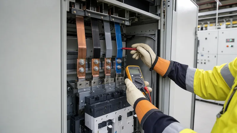
Measuring three-phase voltage requires strict compliance with NFPA 70E and IEC 61010-1 electrical safety standards due to the extreme arc-flash hazards present in low- and medium-voltage distribution equipment. Follow this step-by-step verification procedure using a calibrated digital multimeter (DMM) rated for the appropriate measurement category (typically CAT III 1000 V or CAT IV 600 V minimum):
- Perform a pre-test inspection: Visually inspect personal protective equipment (PPE), including arc-rated face shields, voltage-rated insulating gloves (Class 00 or Class 0), and leather outer protectors. Verify the multimeter test leads are free from cracking, exposed core copper, or insulation damage.
- Prove the meter on a known live source: Follow the "Live-Dead-Live" verification methodology. Measure a known energised source matching the expected voltage magnitude to verify internal multimeter fuses and lead continuity are functional.
- Measure Line-to-Ground potentials: Connect the black reference lead to verified system ground or neutral. Measure each line conductor individually: L1-to-Ground, L2-to-Ground, and L3-to-Ground. In a balanced 400 V system, each reading should register approximately 230 V. If one phase reads zero and the others read 400 V, suspect a corner-grounded delta configuration.
- Measure Phase-to-Phase potentials: Place the probes across phase pairs: L1-to-L2, L2-to-L3, and L3-to-L1. Record the values. All three line-to-line readings must be within 1 to 2 percent of each other under normal supply conditions.
- Check for phase unbalance: Compute the voltage unbalance rate using the NEMA standard equation: percentage unbalance equals the maximum deviation from average voltage divided by average voltage, multiplied by 100. Unbalance exceeding 1 percent degrades motor insulation life through excessive negative-sequence rotor heating.
- Re-test the meter: Immediately touch the meter leads back to the known energised reference source to guarantee the meter remained fully operative during the measurement process.
Transformer Configurations Impacting 3 Phase Output
The physical vector connection of transformer primary and secondary windings dictates the characteristics, grounding availability, and angular phase displacement of the resulting secondary three-phase voltage. The two fundamental winding topologies are Delta (where windings are connected end-to-end forming a closed triangle) and Wye/Star (where one end of each winding terminates at a common neutral junction).
Understanding winding topology is essential when engineering power infrastructure:
- Delta Connection (Δ): Offers high mechanical strength against short-circuit forces and naturally recirculates third-harmonic currents, preventing them from propagating into upstream grids. Delta secondary windings deliver three-wire line-to-line voltage without a stable neutral reference, unless a zig-zag grounding transformer is introduced.
- Wye Connection (Y): Provides a physical neutral point (N) that can be solidly bonded to earth, stabilising system voltages with respect to ground and supporting both single-phase and three-phase loads concurrently. Detailed connection diagrams and phasing rules are covered in our comprehensive guide to delta Y transformer configurations.
- Vector Group Phase Shifts: As standardised under IEC 60076-1, three-phase transformers introduce specific clock-hour phase displacements between primary and secondary line voltages. For instance, in a Dyn11 configuration, the LV wye line voltage lags the HV delta line voltage by 330 degrees (or leads by 30 degrees). For detailed application of vector classifications, refer to our analysis of transformer vector groups explained.
Next steps: specifying and sourcing
Accurate specification of primary and secondary 3 phase voltage parameters is essential to ensure long-term equipment reliability, regulatory compliance, and system efficiency. When requesting quotations for industrial distribution equipment, your technical schedule should clearly state nominal line-to-line voltages, system frequency (50 Hz or 60 Hz), required basic impulse insulation level (BIL), winding vector group, and de-energised tap changer ranges (such as ±2 × 2.5%). Our engineering team manufactures complete power distribution solutions, from medium-voltage distribution transformers to primary switchgear. Explore our certified range of oil-immersed transformers or contact our technical sales desk directly via our transformer quotation page to submit your single-line diagrams and design specifications.
Frequently asked questions
how many volts in three phase
Three-phase low-voltage systems typically deliver either 400 V line-to-line (230 V line-to-neutral) in regions adhering to IEC standards, or 480 V line-to-line (277 V line-to-neutral) and 208 V line-to-line (120 V line-to-neutral) in North America. The specific voltage rating depends on utility grid standards and whether the circuit is measured between phase conductors or to neutral.
Why is 3 phase voltage preferred over single phase for industrial power?
Three-phase power provides continuous, non-pulsating instantaneous power transfer, which allows large AC induction motors to generate a natural rotating magnetic field without auxiliary starting capacitors. Additionally, three-phase conductors deliver 73 percent more electrical power than equivalent single-phase circuits while using less conductor mass.
What happens if three-phase voltages become unbalanced?
Voltage unbalance creates harmful negative-sequence currents inside polyphase electrical motors, resulting in disproportionate thermal heating in rotor bars and stator windings. According to NEMA MG-1 standards, a voltage unbalance of only 3.5 percent can cause motor operating temperatures to increase by 25 percent, requiring significant motor de-rating.
Can you get 240V from a 3 phase supply?
Yes, 240 V three-phase power can be supplied using a dedicated 240 V three-wire delta system or a four-wire 120/240 V centre-tapped "high-leg" delta transformer configuration. In a high-leg delta system, standard 120 V single-phase loads connect between either of the two standard phases and neutral, while 240 V single- or three-phase power is available across the phase legs.
What is the formula to convert 3 phase line voltage to phase voltage?
In a balanced star or wye configuration, phase-to-neutral voltage equals line-to-line voltage divided by the square root of three (approximately 1.732). For example, dividing a 400 V line-to-line measurement by 1.732 yields a phase-to-neutral voltage of 230.9 V.
Why is European three-phase voltage designated as 400V instead of 380V?
The International Electrotechnical Commission harmonised continental European 380 V systems and British 415 V systems under the unified standard IEC 60038 at 400 V (230 V single-phase). Standardising at 400 V nominal with a ±10 percent operating tolerance allowed existing legacy distribution transformers across Europe to operate without immediate capital replacement.
Tags: 3 phase voltage how many volts in three phase european 3 phase voltage transformer configurations industrial power systems


