Key takeaways
- A direct-on-line start draws 6 to 8 times full-load current, while star-delta cuts line current and torque to one third of the DOL values.
- An autotransformer starter on its 65 percent tap reduces line current and starting torque to about 42 percent of DOL, because both scale with tap squared.
- NEC 430.32 sets overload relays at 125 percent of nameplate current for motors with service factor 1.15 or more, and 115 percent for others.
- IEC 60947-4-1 rates contactors by utilization category, with AC-3 for squirrel-cage motors started and stopped while running, and defines Type 1 and Type 2 coordination.
- A 30 kW DOL start on a 100 kVA generator can dip voltage near 30 percent, whereas a soft starter limited to 3 times FLC roughly halves the dip.
Quick answer: A motor starter is a device that safely starts and stops an electric motor and protects it from overload. A magnetic starter combines a contactor, switched by a control circuit, with an overload relay; a manual starter uses a hand-operated switch with built-in overload protection. Reduced-voltage types such as star-delta, autotransformer, soft starters and VFDs limit inrush current on larger three-phase motors.
Connecting a three-phase induction motor straight to the supply works, but the motor draws a burst of current many times its rating, the shaft gets a torque shock, and the supply voltage sags for everything else on the circuit. A motor starter controls that moment and then guards the motor against overload for the rest of its running life.
This guide is for maintenance engineers, panel designers and plant engineers selecting starters for pumps, fans, compressors and conveyors. It explains the purpose of a motor starter, its parts and control circuit, compares the main starter types with their current and torque, and works through a voltage dip example on a transformer and a generator.
What Is the Purpose of a Motor Starter?
A motor starter is an electrical device that switches a motor on and off and provides overload protection, combining a switching element with a protective relay in one assembly. The purpose of a motor starter is fourfold:
- Control: start, stop and in some designs reverse or change speed, locally or remotely.
- Overload protection: trip the motor before sustained overcurrent overheats the windings. Branch-circuit breakers alone do not provide this, because they are sized well above motor full-load current to ride through starting.
- Undervoltage protection: a magnetic starter drops out when voltage fails and will not restart by itself when power returns, which protects people and machinery.
- Inrush limitation, for reduced-voltage starter types.
When is a motor starter required? NEC 430.81 requires a controller for every motor. For small portable motors of 1/3 hp or less, an attachment plug and receptacle can serve as the controller, and for small stationary motors the branch-circuit protective device can serve. Once a continuous-duty motor exceeds 1 hp, NEC 430.32 requires separate overload protection, which in practice means a starter with an overload relay or a motor with integral thermal protection.
An electrical starter for an industrial motor should not be confused with a vehicle's starter motor, which is a small DC motor that cranks an engine. This article covers starters for AC motors in buildings and plants; the motors themselves are covered in our three-phase electric motor guide.
Motor Starter Components: Parts of a Magnetic Starter
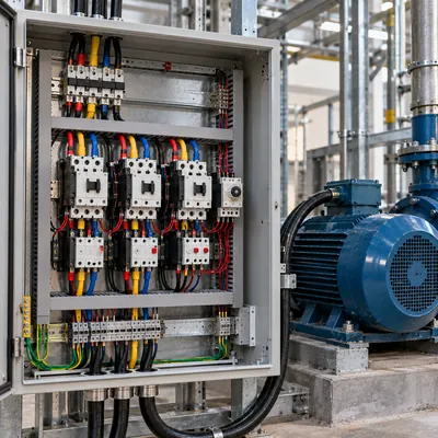
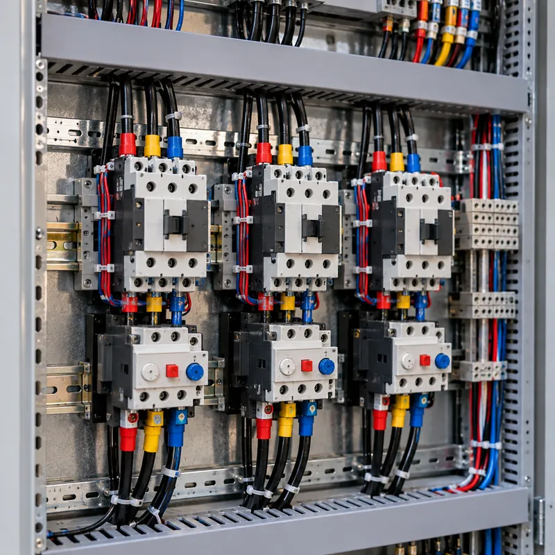
A magnetic motor starter is a starter in which an electromagnetic contactor, energized by a control circuit, closes the power contacts, and an overload relay opens the control circuit on sustained overcurrent. The parts of a motor starter are:
- Contactor: three main power contacts, an operating coil (24 V DC, 120 V AC or 230 V AC typically), and auxiliary contacts for the seal-in circuit and status signals.
- Overload relay: bimetallic thermal or electronic, with an adjustable current setting, trip class (10, 20 or 30 seconds at 600 percent current), reset button and a normally closed contact in the control circuit.
- Short-circuit protection: fuses, an inverse-time breaker or a motor circuit protector ahead of the contactor. When combined in one listed unit this is a combination starter.
- Control devices: start and stop pushbuttons, selector switches, pilot lamps, and often a control power transformer.
- Enclosure, rated as covered in our NEMA enclosure ratings guide.
Manual motor starters replace the contactor and coil with a mechanical switch or a motor protective circuit breaker (MPCB). A manual motor starter, by definition, is a hand-operated device with overload and often short-circuit trip elements. It is compact and cheap, suits small motors up to roughly 15 to 30 kW, but offers no remote control and, in simpler designs, no undervoltage release.
Symbols for these components on schematics are listed in our motor control symbols guide.
How Does a Motor Starter Work? The Control Circuit
The standard motor starter circuit is the three-wire control circuit, named for the three wires between the pushbutton station and the starter. It works like this:
- At rest, control voltage is present at the stop button, which is normally closed. The start button is normally open, so the contactor coil is de-energized.
- Press start: current flows through stop, start and the overload relay's normally closed contact to the coil. The coil pulls in and the main contacts close, connecting the motor to the supply.
- Seal-in: an auxiliary normally open contact on the contactor, wired in parallel with the start button, closes at the same time. When the start button is released, current continues through this holding contact.
- Press stop: the series circuit opens, the coil drops out, and the holding contact opens too. The motor stops and stays stopped.
- Overload trip: if current exceeds the overload setting for long enough, the overload relay's contact opens, dropping out the coil exactly as the stop button does. The relay must be reset before the motor can restart.
- Power failure: the coil drops out and the holding contact opens, so the motor will not restart on its own when power returns. This is called low-voltage protection.
Two-wire control, using a maintained contact such as a float switch or thermostat in place of the pushbuttons, gives automatic restart after power returns; it is used where restart is safe and required. Reversing starters add a second contactor with mechanical and electrical interlocks that swap two phases. Our electrical control panel guide covers PLC-based variants.
Types of Electric Motor Starters Compared
The different types of motor starters trade cost and simplicity against starting current, torque and control. Values below are typical for squirrel-cage induction motors, expressed as a fraction of direct-on-line values.
| Starter type | Starting line current | Starting torque | Typical use |
|---|---|---|---|
| Direct-on-line (DOL) | 100% (6–8 × FLC) | 100% (1.5–2.5 × FLT) | Small and medium motors on stiff supplies |
| Star-delta (wye-delta) | 33% | 33% | Fans, pumps and compressors unloaded at start |
| Autotransformer, 65% tap | 42% | 42% | Large pumps, compressors needing more torque |
| Primary resistor, 70% voltage | 70% | 49% | Smooth start, conveyors |
| Part winding | About 60–65% | About 45–50% | Dual-winding compressor motors |
| Soft starter | Adjustable, often 2–4 × FLC | Proportional to voltage squared | Pumps (water hammer), conveyors, fans |
| Variable frequency drive | About 1–1.5 × FLC | Up to 150% at low speed | Speed control, high-inertia or weak supply |
The key relationship for voltage-reduction methods: motor current is roughly proportional to applied voltage, and torque to voltage squared. Autotransformers are the exception for line current: because the transformer also steps current down, line current falls with tap squared, giving better torque per line ampere than a resistor starter. The star delta starter guide covers the most common reduced-voltage method in detail, including wiring and timing.
Worked Example: Motor Starting Voltage Dip
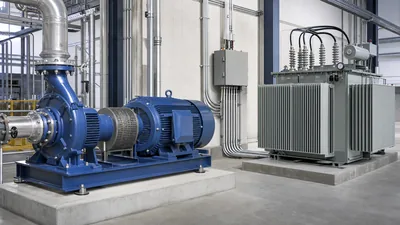
The starter choice often comes down to voltage dip on the supply. A simple estimate treats the source as an impedance and the starting motor as a load of known kVA:
Dip ≈ S_start / (S_sc + S_start), where S_start = √3 × V × I_start and S_sc is the source short-circuit capacity.
Given: a 30 kW, 400 V, 4-pole motor with full-load current of about 56 A and DOL locked-rotor current of 7 × FLC = 392 A.
- Starting kVA:
S_start = 1.732 × 400 × 392 = 272 kVA. - On a 500 kVA transformer with 6 percent impedance:
S_sc = 500 / 0.06 = 8,333 kVA. Dip= 272 / (8,333 + 272) = 3.2%. DOL is acceptable. - On a 100 kVA standby generator with subtransient reactance of about 15 percent:
S_sc = 100 / 0.15 = 667 kVA. Dip= 272 / (667 + 272) = 29%. Contactors elsewhere may drop out and the generator may stall. - With a soft starter limited to 3 × FLC = 168 A:
S_start = 1.732 × 400 × 168 = 116 kVA. Dip= 116 / (667 + 116) = 14.8%. - With a VFD at 1.2 × FLC: dip falls to a few percent, at higher equipment cost and with harmonic considerations.
The method neglects cable impedance and load power factor but is good enough to choose between starter types. For the generator side, see our generator sizing guide.
IEC vs NEMA Motor Starters and Overload Settings
Three-phase motor starters are sold in two design traditions, and both are widely used.
| Aspect | NEMA starters | IEC motor starters |
|---|---|---|
| Rating method | NEMA size (00 to 9), by maximum hp | AC-3 rated current and kW at voltage |
| Design margin | Generous; one size covers wide duty | Sized closely to duty; select by utilization category |
| Physical size | Larger | Compact, DIN-rail mounting common |
| Standards | NEMA ICS 2, UL 60947-4-1 | IEC 60947-4-1 |
| Overload relay | Often interchangeable heaters or electronic | Adjustable thermal or electronic, Class 10 standard |
| Short-circuit coordination | Listed combination ratings | Type 1 or Type 2 coordination tables |
IEC magnetic motor starters should be selected with the right utilization category: AC-3 for squirrel-cage motors started and switched off while running, and AC-4 for plugging, inching and reversing duty, which requires a larger contactor for the same motor.
Overload setting rules under NEC 430.32: set at 125 percent of nameplate full-load current for motors with a service factor of 1.15 or more or a marked temperature rise of 40 °C or less, and 115 percent for all others. Under IEC practice, set the relay to the motor's rated current. Choose trip class 10 for normal starts, class 20 or 30 for high-inertia loads with long acceleration. Before replacing a starter after repeated trips, test the motor itself; see our three-phase motor testing guide.
Next Steps: Specifying and Sourcing Motor Starters
When do I need a motor starter, and which one? Use this sequence:
- Collect motor data: kW or hp, voltage, FLC, service factor, starting current and load torque curve.
- Check supply strength: transformer kVA and impedance, or generator rating, and calculate voltage dip for DOL.
- Choose the starting method from the comparison table: DOL if dip is acceptable, star-delta or soft starter if the load starts unloaded, autotransformer or VFD if torque or process control is needed.
- Select contactor by AC-3 or AC-4 rating, overload relay by FLC and trip class, and short-circuit protection with Type 2 coordination for critical motors.
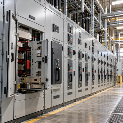
- Decide where starters will live: local panels or a motor control center.
MARS does not sell motor starters as stand-alone retail items. We build them into assemblies: DOL, reversing, star-delta, soft-starter and VFD functional units inside GCS and MNS low-voltage switchboards and motor control centers to IEC 61439-2, routine-tested and with FAT available. See our motor control center guide, explore HV and LV switchgear, and send your motor list through the quote form.
Frequently asked questions
What is the difference between a contactor and a motor starter?
A contactor is an electrically operated switch that opens and closes power circuits. A motor starter is a contactor combined with an overload relay, and often short-circuit protection, so it both controls and protects a motor. Every magnetic starter contains a contactor, but a contactor alone does not protect a motor.
What are the main types of motor starters?
The main types are manual starters, direct-on-line magnetic starters, reversing starters, star-delta starters, autotransformer starters, primary resistor starters, part-winding starters, soft starters and variable frequency drives. The first three apply full voltage; the others reduce starting current and torque in different ways.
When is a motor starter required?
NEC 430.81 requires a controller for every motor, and NEC 430.32 requires overload protection for continuous-duty motors above 1 hp. In practice any three-phase motor, and most single-phase motors above 1 hp, need a starter with an overload relay unless the motor has listed integral thermal protection.
How does a magnetic starter work?
Pressing start energizes the contactor coil, which closes the main contacts and an auxiliary seal-in contact that keeps the coil energized after the button is released. Pressing stop or an overload trip opens the coil circuit, the contactor drops out, and the motor stops and will not restart automatically after a power failure.
What size overload should I set on a motor starter?
Under NEC 430.32, set the overload relay at 125 percent of nameplate full-load current for motors with a service factor of 1.15 or higher or a 40 °C rise, and 115 percent for others. IEC practice sets the relay to the motor rated current. Choose trip class 10, 20 or 30 to match acceleration time.
Is a soft starter better than a star delta starter?
A soft starter gives a smooth, adjustable voltage ramp with no current spike at transition and allows soft stopping to reduce water hammer in pumps. A star-delta starter costs less and generates no harmonics but has a fixed one-third torque and a transient at changeover. Choose by load, supply and budget.
Written and reviewed by the MARS application engineering team in Shanghai, who specify and test transformers, switchgear, substations and battery storage for projects in 40+ countries. Last updated .
Tags: motor starter magnetic motor starter 3 phase motor starter manual motor starters iec motor starter