Key takeaways
- Transformer insulation defines the dielectric barrier and thermal endurance of a unit, directly governing its operating lifespan and short-circuit withstand capabilities.
- IEC 60076-11 and IEEE C57.12.01 categorise dry-type transformer insulation systems into standard thermal classes, including Class 130 (B), Class 155 (F), Class 180 (H), and Class 220 (C).
- Operating a transformer 8 °C to 10 °C continuously above its thermal insulation rating halves the expected operating lifespan of the dielectric material through accelerated thermal ageing.
- Partial discharge limits for cast resin dry-type transformer insulation must remain below 10 pC at 1.3 times rated phase-to-ground voltage under IEC 60076-11 routine acceptance testing.
- Vacuum pressure impregnation (VPI) and vacuum cast resin (CRT) represent the two primary solid insulation methodologies used in modern medium-voltage dry-type installations.
Quick answer: Transformer insulation provides the necessary dielectric strength to isolate high-voltage conductors from ground and adjacent phases while handling continuous thermal stress. Modern dry type transformer insulation systems rely on solid composite materials rated to thermal classes such as Class 155 (F), Class 180 (H), or Class 220 (C) under IEC 60076-11 and IEEE C57.12.01 standards.
In electrical distribution systems, the selection of the correct dielectric insulation system directly dictates equipment lifespan, footprint, overload headroom, and operational safety. Unlike liquid-filled units that utilise mineral oil or synthetic esters, dry-type units depend entirely on solid barriers and ambient air dissipation. Consequently, selecting the appropriate solid insulation medium requires balancing electrical stress, atmospheric contamination, mechanical vibration, and peak operating temperatures.
Engineers specifying plant for commercial buildings, data centres, and industrial facilities must assess whether vacuum pressure impregnation or cast resin encapsulation provides the required operational reliability. This guide examines thermal limits, degradation mechanisms, material selection, and testing methodologies for medium-voltage dry-type transformer insulation.
Thermal Classes and Limits for Transformer Insulation
Thermal endurance governs the classification of transformer insulation, determining how hot the winding system can operate continuously without premature degradation. International standards, specifically IEC 60076-11 and IEEE C57.12.01, define performance thresholds based on a standard maximum ambient temperature of 40 °C and an average daily ambient of 30 °C.
Specifying an insulation system involves three parameters: the maximum ambient temperature, the allowable average winding temperature rise measured by resistance, and the hot-spot allowance. Exceeding these thermal thresholds accelerates polymer chain scission in solid barriers, causing brittleness, delamination, and dielectric breakdown. For a comprehensive overview of complete unit topologies, refer to the Dry Type Transformer Guide: Types, Specs, Sizing & Selection.
The table below summarises the primary thermal classes utilised in dry type transformer insulation systems in accordance with IEC 60076-11:
| Thermal Class (Letter / Number) | Maximum Ambient Temp (°C) | Average Winding Rise Limit (°C) | Hot-Spot Temperature Rise (°C) | Maximum Hot-Spot Limit (°C) | Typical System Chemistry |
|---|---|---|---|---|---|
| Class 105 (A) | 40 | 60 | 65 | 105 | Kraft paper, pressboard, shellac |
| Class 130 (B) | 40 | 80 | 90 | 130 | Inorganic materials with organic binders |
| Class 155 (F) | 40 | 100 | 110 | 155 | Modified epoxy resin, woven glass cloth |
| Class 180 (H) | 40 | 125 | 145 | 180 | High-temp epoxy, silicone resin, aramid paper |
| Class 220 (C / R) | 40 | 150 | 180 | 220 | Pure mica, porcelain, advanced aramid composites |
Specifying a Class 155 (F) system with a Class 130 (B) temperature rise provides built-in thermal margin. This conservative engineering practice delivers significant overload capacity and extends insulation life under unventilated, high-ambient installations.
Types of Dry Type Transformer Insulation Systems
The two prevailing dry type transformer insulation methodologies are vacuum pressure impregnated (VPI) systems and vacuum cast resin (CRT) encapsulations. Each methodology solves dielectric and mechanical challenges differently, altering suitability for harsh environments.
Vacuum pressure impregnated transformers utilise pre-formed coils wrapped with non-hygroscopic aramid papers, mica tapes, or woven glass tapes. Once assembled, the windings undergo a thermal pre-heating cycle under deep vacuum to extract all moisture and entrained air. A high-temperature polyester or silicone varnish is then injected under hydraulic pressure, filling porous gaps and micro-voids. VPI transformers provide superior thermal convection and mechanical flexibility, making them widely deployed in clean commercial infrastructure and industrial motor control centres.
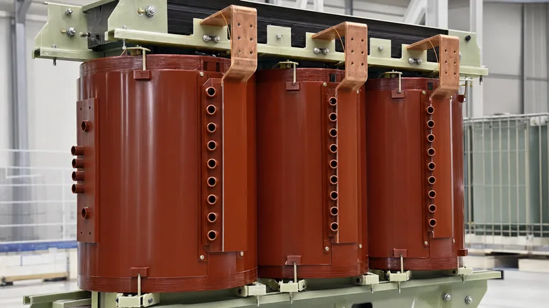
Cast resin transformers, detailed in our Cast Resin Transformer Guide: Specs, Classes & Selection, utilise high-voltage windings cast inside aluminium or steel moulds under a tight vacuum. The encapsulating medium comprises a liquid bisphenol-epoxy resin blended with silica powder (quartz flour) and an alumina trihydrate fire-retardant filler. The cured resin block provides monolithic mechanical rigidity and absolute encapsulation, yielding exceptional resistance to moisture, chemical fumes, and heavy particulate deposition.
Where VPI units rely on creepage distances across coated paper surfaces, cast resin designs eliminate air interfaces around the primary conductor, making them the standard choice for marine vessels, chemical processing plants, and unconditioned outdoor enclosures.
Degradation Mechanisms and Thermal Ageing Calculations
Degradation of transformer insulation is primarily driven by thermal stress, mechanical fatigue, partial discharge, and ambient moisture contamination. The chemical breakdown of solid organic insulation follows the classical Arrhenius reaction rate theory, where elevated temperature accelerates chemical degradation.
Montsinger's empirical rule states that for every 8 °C to 10 °C increase in winding hot-spot temperature above the thermal limit, the rate of insulation life consumption doubles, cutting operating life in half. Monitoring internal conditions is crucial, as explored in the Winding Temperature Guide: Transformer Thermal Limits. Mechanical stresses during through-fault short circuits exert tremendous electromagnetic forces on the coil conductors; brittle or thermally degraded insulation easily shatters under these radial and axial forces, triggering instantaneous inter-turn flashovers.
Consider this thermal ageing calculation for a Class 155 (F) rated dry type transformer operating in an unventilated switchroom:
- Rated Design Limit: Hot-spot reference temperature θ_ref = 155 °C for a nominal 20-year (175,200 hour) design lifespan.
- Operating Condition: Blocked air intake louvres elevate ambient temperature to 50 °C, driving continuous winding hot-spot temperature θ_actual to 171 °C (Δθ = +16 °C above design base).
- Arrhenius Half-Life Factor: Assuming life consumption doubles for every 8 °C rise (n = 16 / 8 = 2 doublings).
- Relative Ageing Rate (V): V = 2^(Δθ / 8) = 2^(16 / 8) = 2^2 = 4.0.
- Effective Service Life: 20 years / 4.0 = 5.0 years.
Operating this unit just 16 °C above its nominal rating cuts the expected asset lifespan from 20 years down to merely 5 years, highlighting why thermal monitoring and accurate cooling specifications are non-negotiable.
Partial Discharge and Dielectric Withstand in Solid Insulation
Partial discharge (PD) represents the primary electrical degradation mechanism in solid dry type transformer insulation systems. A partial discharge is a localised electrical breakdown that only partially bridges the insulation between conductors, occurring within internal gas cavities, micro-voids, or delaminated interfaces within the resin composite.
Because the relative permittivity (dielectric constant) of air or entrained gas (ε_r ≈ 1.0) is considerably lower than that of cured epoxy resin (ε_r ≈ 3.5 to 4.2), the electric field strength concentrating across internal voids is amplified. If this concentrated gradient exceeds the breakdown field strength of the trapped gas, micro-arcs ignite. These discharges generate ozone, ultraviolet radiation, and nitric acid, steadily eroding the surrounding resin matrix through mechanical treeing until full dielectric puncture occurs.
IEC 60076-11 clause 22 sets rigorous acceptance criteria for partial discharge testing during factory acceptance procedures. Dry-type cast resin coils must exhibit a PD magnitude of less than 10 pC (picocoulombs) when tested at 1.3 times the maximum rated operating line-to-ground voltage. Routine factory dielectric testing also mandates a separate-source power-frequency AC withstand test and an induced overvoltage test at twice the rated voltage and frequency to confirm dielectric integrity before delivery. Practical methodologies for field and factory verification are detailed in the guide on Power Transformer Testing: Factory & Acceptance Guide.
Factory Specification and Procurement Checklist
Specifying transformer insulation requires explicit technical parameters in tender documents to prevent suppliers from substituting inferior thermal materials or omitting critical dielectric verifications. Engineers must establish exact environmental, mechanical, and thermal constraints during the RFQ phase.
Use the following technical checklist when preparing technical schedules for dry-type medium-voltage equipment:
- Standards Compliance: State IEC 60076-11 or IEEE C57.12.01 compliance explicitly, including mandatory routine, type, and special test reports.
- Insulation Class & Rise Combination: Specify thermal margins where relevant, such as Class 180 (H) materials designed to Class 155 (F) temperature rise limits (maximum 100 K average rise).
- Environmental, Climatic, and Fire Behavior Classes: Mandate environmental class E2 (frequent condensation/pollution) or higher environmental classes for industrial sites, climatic class C2 (-25 °C) or C3 (-40 °C), and fire behaviour class F1 (self-extinguishing, zero halogen).
- Partial Discharge Limits: Stipulate maximum permissible PD ≤ 10 pC at 1.3 × U_m / √3, verified via multi-channel digital PD detectors inside shielded factory test cells.
- Basic Impulse Level (BIL): Specify full-wave lightning impulse withstand ratings; for example, 95 kV or 125 kV BIL for standard 24 kV distribution networks.
- Enclosure Protection Index: Require IP21 to IP31 for internal clean rooms, or minimum IP54 with air-to-air heat exchangers for harsh, dusty, or outdoor configurations.
- Temperature Sensors: Include PT100 platinum RTDs embedded directly into the hot-spot area of each low-voltage winding phase, pre-wired to an electronic monitoring relay.
Next Steps: Specifying and Sourcing
Selecting the optimal transformer insulation requires a rigorous assessment of ambient temperatures, harmonic load profiles, pollution severities, and planned asset lifespans. Oversizing thermal capacity delivers dividends through extended operating life and high overload tolerance.
Explore our complete range of certified medium-voltage distribution systems on our dry-type transformer product page and review integrated substation configurations on our transformer substation page. When preparing your project schedule, forward single-line diagrams, ambient environmental conditions, and loss evaluation criteria to our engineering team via our contact page or submit a direct RFQ on our quote page to receive a fully calculated technical proposal.
Frequently asked questions
What is transformer insulation made of?
Transformer insulation in dry-type units consists of solid dielectric materials such as aramid composite papers, woven fiberglass tapes, silica-filled epoxy cast resins, and silicone varnishes. In liquid-filled units, cellulose kraft paper combined with mineral oil or natural ester fluid serves as the insulation system.
What is the difference between Class F and Class H transformer insulation?
Class F insulation allows a maximum continuous operating hot-spot temperature of 155 °C with a rated 100 °C winding temperature rise over a 40 °C ambient. Class H permits a higher hot-spot temperature of 180 °C with a 125 °C winding rise, offering superior overload capacity and thermal endurance.
How does moisture affect dry type transformer insulation?
Moisture creates conductive surface tracking pathways across solid insulation barriers and reduces the dielectric breakdown voltage of the dry-type transformer insulation system. In unsealed units, moisture absorption can accelerate partial discharge activity and lead to flashover upon energisation after shutdown.
Why is partial discharge testing critical for transformer insulation?
Partial discharge testing identifies microscopic voids and manufacturing defects within the solid resin insulation before equipment leaves the factory floor. Undetected partial discharges slowly degrade solid dielectric materials over operating cycles, ultimately causing premature internal dielectric puncture and total phase-to-ground faults.
What is the 10-degree rule in transformer insulation?
The 10-degree rule, derived from the Arrhenius chemical reaction rate, states that operating an insulation system 8 °C to 10 °C continuously above its rated thermal limit cuts the transformer's expected operational life in half. Conversely, operating 10 °C below the thermal limit roughly doubles insulation lifespan.
Tags: transformer insulation dry type transformer insulation insulation class cast resin transformer dielectric strength


