Key takeaways
- Galvanic isolation means no conductive path between circuits; energy crosses the gap magnetically while insulation withstands test voltages defined in standards such as IEC 61558.
- Most isolation transformers are 1:1, for example 240 V to 240 V or 480 V to 480 V, but any two-winding transformer provides isolation.
- An electrostatic (Faraday) shield between windings, bonded to ground, diverts capacitively coupled common-mode noise away from the secondary.
- Under NEC 250.30, a grounded isolation transformer secondary is a separately derived system needing its own system bonding jumper and grounding electrode conductor.
- A 240 V, 32 A single-phase load draws 7.7 kVA, so a 10 kVA isolation transformer gives margin for inrush, harmonics and future load.
Quick answer: An isolation transformer is a transformer with physically separate primary and secondary windings, usually at a 1:1 ratio, that transfers power magnetically with no direct conductive path between input and output. This galvanic isolation improves shock protection, breaks ground loops, attenuates common-mode noise when an electrostatic shield is fitted, and lets the secondary be grounded as a new separately derived system.
Isolation transformers are often bought for the wrong reason and then blamed for not solving the problem. They do not regulate voltage, they do not remove every kind of noise, and on their own they do not make a circuit safe to touch. What they do, very well, is break the conductive path between two systems and give the engineer a clean slate for grounding.
This guide is for facility engineers, panel builders, medical and laboratory planners, and anyone specifying a dry-type isolation transformer. It covers the working principle, the purposes that justify one, shielding and grounding choices, NEC and IEC requirements, and a worked sizing example.
What Is an Isolation Transformer and Galvanic Isolation?
Galvanic isolation is the separation of two electrical circuits so that no direct current path exists between them, while energy or signals still pass by magnetic, capacitive or optical coupling. An isolation transformer is a power transformer designed specifically to provide galvanic isolation between its supply and its load, usually without changing the voltage.
Strictly, every two-winding transformer provides galvanic isolation in transformers: a 13.8 kV to 480 V distribution unit isolates the plant from the utility conductors. What distinguishes a product sold as an iso transformer is the emphasis on that function:
- A 1:1 voltage ratio, such as 120 V to 120 V, 240 V to 240 V, 400 V to 400 V or 480 V to 480 V.
- Enhanced insulation between windings, often double or reinforced insulation in IEC 61558-2-4 (isolating transformers) or IEC 61558-2-6 (safety isolating transformers) designs.
- One or more electrostatic shields between windings.
- Low interwinding capacitance and controlled leakage current.
The contrast with an autotransformer is complete: an autotransformer shares a winding between input and output and provides no isolation at all, as explained in our autotransformer guide. If isolation is the goal, the device must have separate windings.
Galvanic isolation also exists in electronics, through optocouplers, digital isolators and the high-frequency transformers inside switch-mode supplies. The principle is the same; the scale differs.
Isolation Transformer Working Principle
The isolation transformer working principle is ordinary electromagnetic induction. Alternating current in the primary creates alternating flux in the core; that flux links the secondary and induces a voltage given by V = 4.44 × f × N × A × B. With equal turns, the secondary voltage matches the primary, less a small regulation drop under load.
Three coupling paths exist between windings, and only one is wanted:
- Magnetic coupling through the core transfers the 50 or 60 Hz power. This is the useful path.
- Capacitive coupling through the interwinding capacitance passes high-frequency noise and surges, especially common-mode disturbances appearing between lines and ground.
- Insulation leakage, which is minimal in a healthy unit and is verified by dielectric tests.
An electrostatic shield, a thin copper or aluminium foil wound between primary and secondary and bonded to ground, intercepts the capacitive path. Common-mode noise current flows into the shield and to ground instead of into the secondary. Units with multiple shields are sometimes marketed as ultra-isolation transformers. Shielding does little for normal-mode (line-to-line) noise, which passes magnetically like the power itself; that needs filters or a low-impedance design.
The core and winding physics are identical to any distribution transformer; only the insulation and shielding emphasis differ.
Isolation Transformer Purpose: Where It Is Used
The isolation transformer purpose varies by industry. Typical isolation transformer uses include:
- Shock protection by electrical separation. If the secondary is left floating (not grounded) and supplies a single item of equipment, a person touching one secondary conductor and ground does not complete a circuit. This is the principle of electrical separation in IEC 60364-4-41 and of shaver sockets and workshop test benches.
- Medical IT systems. Operating rooms use ungrounded isolated power systems so that a first insulation fault does not trip supply. IEC 60364-7-710 and NEC Article 517 require insulation monitoring or line isolation monitors to alarm on the first fault.
- Separately derived systems. A 480 V delta to 480Y/277 V isolation transformer creates a new neutral and ground reference for a building or a sensitive load.
- Drive isolation. Variable frequency drives and DC drives are often fed through isolation transformers to limit common-mode voltage, reduce harmonics reaching the supply and provide impedance; see our K-factor transformer guide for harmonic rating.
- Marine shore power. Shore connections use isolation transformers to stop galvanic corrosion currents between vessel and shore grounds.
- Laboratories, data and audio systems. Breaking ground loops and attenuating common-mode noise.
The function of an isolation transformer in each case is to control where fault current, leakage current and noise current can flow. Defining that clearly is the first step in specifying one.
Ground Isolation Transformer: Grounding the Secondary
A ground isolation transformer is any isolation transformer used to separate the ground reference of one system from another. How the secondary is grounded determines safety and code compliance, and it is where most installation errors occur.
| Secondary arrangement | Behaviour | Typical use | Key requirement |
|---|---|---|---|
| Grounded (wye or one leg) | New separately derived system; ground fault trips OCPD | Building feeders, sensitive electronics, drives | NEC 250.30 system bonding jumper and grounding electrode conductor |
| Ungrounded, monitored (IT) | First fault does not trip; alarm raised | Operating rooms, some industrial processes | Insulation monitoring device or line isolation monitor |
| Ungrounded, single load (electrical separation) | Touch on one conductor gives no shock path | Test benches, shaver supplies, portable tools | Limited cable length and one load per IEC 60364-4-41 |
In the grounded case, the neutral-to-ground bond is made at the transformer secondary or at the first disconnect, and only once. Bonding again at downstream panels creates parallel neutral current paths and objectionable current. Our transformer grounding system guide details electrode and bonding options, and neutral to ground voltage explains why a local bond reduces N-G voltage at sensitive equipment.
The shield terminal must also be bonded, normally to the equipment grounding conductor at the transformer. A floating shield can couple noise rather than block it. Any work on service or feeder equipment must follow local code and be carried out by a licensed electrician.
Isolation Transformer 240V to 240V: Sizing Example
The isolation transformer 240V to 240V request is common for single-phase loads such as laboratory benches, imported machines and medical carts. Size by kVA, not by watts, and allow for inrush and harmonics.
Step 1, load kVA. A 240 V machine draws 32 A at full load: S = V × I = 240 × 32 = 7,680 VA = 7.7 kVA.
Step 2, margin. Continuous loads should not exceed about 80% of nameplate for comfortable temperature rise and room for growth: 7.7 / 0.8 = 9.6 kVA. Select the next standard size, 10 kVA. If the load is a rectifier or drive with high harmonic current, consider a K-rated design.
Step 3, currents. Primary and secondary current at full rating: 10,000 / 240 = 41.7 A each side.
Step 4, overcurrent protection. Under NEC 450.3(B), primary-only protection for currents of 9 A or more is 125% of rated primary current, rounded up to the next standard size: 41.7 × 1.25 = 52 A, so 60 A is permitted. Secondary conductors still need protection under NEC 240.21(C). Our transformer fuse sizing guide explains both methods.
Step 5, short-circuit check. With 3% impedance, secondary bolted fault current is about 41.7 / 0.03 = 1,390 A (infinite source), which limits downstream fault duty.
| Rating (single-phase) | 240 V current | 480 V primary current |
|---|---|---|
| 3 kVA | 12.5 A | 6.3 A |
| 5 kVA | 20.8 A | 10.4 A |
| 10 kVA | 41.7 A | 20.8 A |
| 15 kVA | 62.5 A | 31.3 A |
| 25 kVA | 104 A | 52.1 A |
For a smaller bench supply, see our 5 kVA transformer guide.
Isolated Power Transformer Types and Construction
An isolated power transformer can be built several ways, and the construction should match the duty.
- Encapsulated LV dry-type (typically up to about 15–25 kVA): core and coils potted in resin, good for dusty or damp locations and outdoor NEMA 3R enclosures.
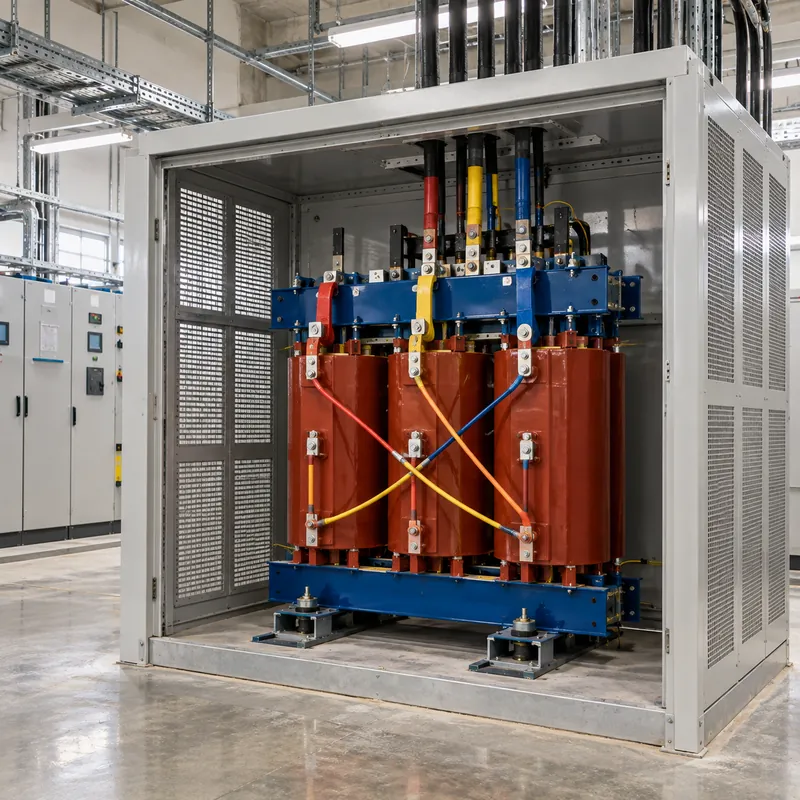
- Ventilated LV dry-type (15 kVA to several hundred kVA): open windings cooled by natural air, the usual choice for building and drive isolation.
- Cast-resin MV/LV transformers: for isolating whole buildings, data halls or process areas from a medium-voltage supply; see our dry type transformer guide.
- Toroidal isolation transformers for equipment below a few kVA, valued for low stray field; covered in our toroidal transformer guide.
- Medical-grade units with low leakage current, enhanced insulation and temperature monitoring for IT systems.
Insulation class (for example 180 °C class H or 220 °C class R) and temperature rise determine life and overload tolerance. Three-phase drive isolation transformers are commonly delta primary and wye secondary, which also blocks triplen harmonics from reaching the supply. For three-phase 480 V systems the same sizing logic as above applies with I = S / (√3 × V).
Remember what an isolation transformer will not do: it does not regulate voltage, ride through outages or remove normal-mode harmonics. For those, add voltage regulation, UPS or storage, or filtering.
Next Steps: Specifying and Sourcing
A complete isolation transformer RFQ should state:
- Rating in kVA, single- or three-phase, frequency (50 or 60 Hz).
- Primary and secondary voltages and connections, e.g., 480 V delta to 480Y/277 V, or 240 V to 240 V.
- Secondary grounding intent: grounded separately derived system, monitored IT, or floating single load.
- Shielding: none, single or multiple electrostatic shields, and required shield terminal.
- Load type and harmonic content (K-factor), inrush characteristics and duty cycle.
- Impedance target, insulation class, temperature rise and any efficiency requirement.
- Enclosure: indoor ventilated, encapsulated, IP or NEMA rating, ambient and altitude.
- Standards: IEC 60076-11 or IEC 61558 series, IEEE C57.12.01 and UL listing needs.
MARS manufactures dry-type transformers, including cast-resin units for drive and data center supplies (state any shielding requirement in the RFQ for engineering review), and compact substations where a full MV/LV isolation point is required. Units are routine-tested, FAT witness is welcome and typical lead time is 25–45 days. Send your requirement through the quote page.
If the isolation transformer is being added to solve an existing noise or nuisance-tripping problem, include a short description of the symptoms and any power quality measurements. That helps confirm whether isolation, shielding, K-rating or a different measure is actually the right fix.
Frequently asked questions
What is the purpose of an isolation transformer?
The purpose of an isolation transformer is to separate two electrical systems galvanically, so no conductive path exists between supply and load. This allows a new grounding reference, reduces shock risk when the secondary floats, breaks ground loops, attenuates common-mode noise with an electrostatic shield and limits fault and leakage current paths for sensitive, medical or drive equipment.
Does an isolation transformer protect against electric shock?
An isolation transformer reduces shock risk only when its secondary is ungrounded and supplies a limited circuit, because touching one conductor and earth does not complete a path. A second fault or a grounded secondary removes that benefit. It does not replace RCDs, proper bonding or safe work practices, and any work on live equipment must follow NFPA 70E or local rules.
Is an isolation transformer the same as a 1:1 transformer?
Most isolation transformers are 1:1, but the defining feature is separate primary and secondary windings, not the ratio. Any two-winding transformer, including a 480 V to 208Y/120 V unit, provides galvanic isolation. Products sold as isolation transformers usually add electrostatic shielding, enhanced interwinding insulation and low leakage current to optimise the isolation function.
Do I need to ground the secondary of an isolation transformer?
It depends on the purpose. For building or equipment supply in North America, the secondary is normally grounded as a separately derived system under NEC 250.30, with a system bonding jumper and grounding electrode conductor. Ungrounded secondaries are used for medical IT systems with insulation monitoring and for electrical separation of single loads under IEC 60364-4-41.
What is galvanic isolation in transformers?
Galvanic isolation in transformers means the primary and secondary windings are electrically insulated from each other, so energy passes only through the shared magnetic flux in the core. No DC path exists between the circuits. The insulation is verified by applied-voltage dielectric tests, and its level determines whether the transformer qualifies as basic, double or reinforced insulation.
Does an isolation transformer reduce electrical noise?
A shielded isolation transformer reduces common-mode noise, which couples capacitively between windings, by diverting it through a grounded electrostatic shield. It also creates a local neutral-to-ground bond that lowers neutral-to-ground voltage at equipment. It does little against normal-mode noise or harmonics, which pass magnetically, so filters or K-rated designs may be needed as well.
Written and reviewed by the MARS application engineering team in Shanghai, who specify and test transformers, switchgear, substations and battery storage for projects in 40+ countries. Last updated .
Tags: isolation transformer galvanic isolation isolation transformer purpose isolation transformer 240v to 240v ground isolation transformer