Key takeaways
- A 480Y/277 V system has 480 V line-to-line and 277 V line-to-neutral, because line voltage equals phase voltage multiplied by 1.732 in a wye connection.
- A 20 A, 277 V lighting circuit loaded to the 80 percent continuous limit supplies 4,432 W, compared with 1,920 W on a 120 V circuit.
- NEC 230.95 requires ground-fault protection of equipment on solidly grounded wye services of 1,000 A or more with more than 150 V to ground, which includes 480Y/277 V.
- A 1,500 kVA pad-mounted transformer at 480 V supplies 1,804 A of secondary full-load current, and a 2,500 kVA unit about 3,007 A.
- High-resistance grounded 480 V systems keep running after a first ground fault, but NEC 250.36 prohibits serving line-to-neutral 277 V loads from them.
Quick answer: 277/480V 3 phase is a four-wire wye system with 480 V between any two phase conductors and 277 V from each phase to the grounded neutral, since 480 / √3 = 277 V. It is the standard service for large US commercial and industrial buildings: 480 V feeds motors and HVAC, 277 V single-phase feeds lighting, and dry-type transformers step down to 208Y/120 V for receptacles.
Walk into the electrical room of almost any US hospital, warehouse, office tower or factory and the main switchboard will be rated 480Y/277 V. The system carries large loads on modest current, feeds lighting directly at 277 V and steps down locally for 120 V outlets. It is efficient, but it also brings higher arc-flash energy and specific grounding and protection rules.
This guide explains how the 277/480 V three-phase system is derived, what each voltage is used for, how single-phase 277 V circuits work, and how to size and specify the transformers that supply and follow it. It is for electrical designers, facility engineers and contractors working on 60 Hz commercial and industrial projects.
What Is a 277/480V 3-Phase System?
A 480Y/277 V system is a three-phase, four-wire, solidly grounded wye system. The supply transformer secondary has three windings, each producing 277 V, connected in a star with the common point grounded and brought out as the neutral.
The phase voltages are displaced 120 degrees, so the voltage between any two lines is:
VLL = √3 × VLN = 1.732 × 277 = 480 V
| Measurement | Nominal voltage | Used for |
|---|---|---|
| A-B, B-C, C-A | 480 V | Three-phase motors, chillers, air handlers, large single-phase loads |
| A-N, B-N, C-N | 277 V | Fluorescent and LED lighting, some heaters, signage |
| Any phase to ground | 277 V | Same as L-N in a solidly grounded system |
| Neutral to ground | Near 0 V | Bonded at service disconnect |
The naming 277/480, 480/277 and 480Y/277 all mean the same system; ANSI C84.1 writes it 480Y/277 V. Equipment nameplates usually show 460 V for motors and 277 V for luminaires, reflecting utilization voltage. The 480 V level in general, including delta variants, is covered in the 480V 3-phase power guide.
Why not use 208Y/120 V everywhere? Because for the same load, 480 V carries 43 percent of the current that 208 V does. A 1 MW load at PF 0.9 needs 1,000,000 / (1.732 × 480 × 0.9) = 1,336 A at 480 V but 3,084 A at 208 V.
Single-Phase 277 V Circuits: Lighting and Beyond
A single-phase 277 V circuit connects one phase conductor and the neutral from a 480Y/277 V panelboard. It is the backbone of commercial lighting because it carries more than twice the power of a 120 V circuit on the same conductor size.
Worked example: a 20 A branch circuit at 277 V, limited to 80 percent for continuous lighting load (16 A), supplies 277 × 16 = 4,432 W. At 120 V the same circuit supplies 120 × 16 = 1,920 W. A warehouse with 120 kW of LED high-bay lighting needs about 28 circuits at 277 V versus about 63 at 120 V.
- Voltage drop: for the same power, current at 277 V is 43 percent of that at 120 V, and percentage voltage drop is about 19 percent of the 120 V value on the same conductor.
- Balance: distribute 277 V circuits evenly across A, B and C to keep the neutral current low.
- Harmonics: LED drivers and electronic ballasts produce third-harmonic currents that add in the neutral instead of cancelling. In large lighting systems the neutral can carry up to 1.73 times phase current in extreme cases; specify full-size or oversized neutrals.
Single phase 277 is also used for water heaters and some heat-trace and unit heaters rated 277 V. Equipment must be specifically rated for it; a 240 V device on 277 V sees 15 percent overvoltage.
For receptacles and 120 V loads in a 277/480 V building, a step-down transformer is needed. A dedicated 277 V to 120 V single-phase unit can serve small loads; see the 277 to 120 transformer guide.
What Loads Run on 480 V Three-Phase?
The 480 V line-to-line voltage feeds the large mechanical and process loads that define commercial and industrial buildings.
- Motors: pumps, fans, compressors and conveyors with 460 V nameplates. A 50 hp motor draws 65 A at 460 V per NEC Table 430.250, compared with 143 A at 208 V nameplate 200 V.
- HVAC: chillers, rooftop units, air handlers and cooling towers.
- Elevators and escalators.
- Process equipment: injection molding, ovens, welders and machine tools.
- EV fast chargers and UPS systems, which commonly take 480 V three-phase input.
- Feeders to step-down transformers for 208Y/120 V panels.
480 V delta three-wire systems, without a neutral, are also used in industrial plants where no 277 V loads exist. The detailed voltage tolerance and motor nameplate relationships are explained in the 460V 3-phase guide.
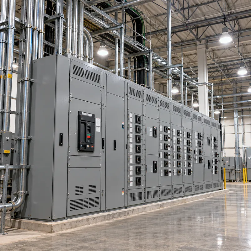
A typical large building single-line diagram has a utility pad-mounted transformer with 480Y/277 V secondary, a main switchboard with ground-fault protected main breaker, distribution sections feeding motor control centers and 480Y/277 V lighting panels, and dry-type transformers of 30 to 225 kVA feeding 208Y/120 V receptacle panels on each floor.
How to Step Down 480Y/277 V to 208Y/120 V
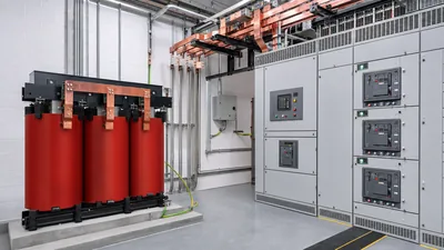
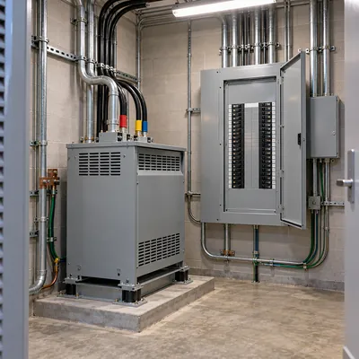
Every 480Y/277 V building needs 120 V somewhere. The usual solution is a three-phase dry-type transformer with 480 V delta primary and 208Y/120 V wye secondary, located close to the receptacle panels it serves.
- Total the 120 V and 208 V loads on the panel, applying NEC Article 220 demand factors.
- Add growth and harmonic allowance: 20 to 25 percent spare, and K-factor rating (K-4 or K-13) if IT loads dominate.
- Select kVA: standard sizes 15, 30, 45, 75, 112.5, 150 and 225 kVA.
- Size primary protection per NEC 450.3(B): up to 125 percent of primary current for primary-only protection, or up to 250 percent when secondary protection is set at no more than 125 percent, with the next-size-up allowances in the table notes.
- Ground the secondary: the transformer is a separately derived system, so bond the secondary neutral to ground per NEC 250.30 with a properly sized system bonding jumper and grounding electrode conductor.
- Check fault current on the secondary panel based on transformer impedance.
Example: a floor has 55 kVA of demand at 208Y/120 V. With 25 percent margin, 68.8 kVA, so a 75 kVA unit. Primary current is 75,000 / (1.732 × 480) = 90.2 A; secondary current is 75,000 / (1.732 × 208) = 208 A, feeding a 225 A panel. Wiring diagrams for this connection are in the 480 to 208 transformer wiring diagram.
Grounding, Ground-Fault Protection and Arc Flash at 480Y/277 V
At 277 V to ground, arcing faults sustain themselves far more readily than at 120 V. The NEC and NFPA 70E impose specific requirements as a result.
Ground-fault protection of equipment
NEC 230.95 requires ground-fault protection on solidly grounded wye services with more than 150 V to ground and not exceeding 1,000 V phase-to-phase, for service disconnects rated 1,000 A or more. The maximum setting is 1,200 A, with a maximum delay of one second for faults of 3,000 A or more. NEC 215.10 and 240.13 extend similar requirements to feeders and building disconnects. Hospitals require an additional level of GFP under NEC 517.17.
Arc flash
Incident energy is calculated with IEEE 1584, and NFPA 70E sets the labeling and PPE rules. 480 V switchboards fed by large transformers often exceed 8 cal/cm² at working distance. Reducing clearing time with zone-selective interlocking, maintenance mode switches or current-limiting fuses is the most effective mitigation, reviewed in 480 V arc flash incident energy mitigation.
High-resistance grounding
Industrial plants sometimes use high-resistance grounded (HRG) 480 V systems, which limit ground-fault current to a few amps and allow continued operation. NEC 250.36 permits HRG systems only where no line-to-neutral loads are served, so 277 V lighting must then come from separate transformers.
| Grounding method | 277 V loads allowed | First ground fault |
|---|---|---|
| Solidly grounded wye | Yes | Trips immediately |
| High-resistance grounded wye | No | Alarm, continue running |
| Ungrounded delta | No neutral | Alarm via ground detectors |
277/480 V vs 208Y/120 V: Which Service for a Building?
The choice between the two standard US wye systems depends mainly on building size and load type.
| Criterion | 480Y/277 V | 208Y/120 V |
|---|---|---|
| Current for 1,000 kVA | 1,203 A | 2,776 A |
| Lighting circuits | 277 V, 4.4 kW per 20 A circuit | 120 V, 1.9 kW per 20 A circuit |
| Receptacles | Need step-down transformers | Direct |
| Motors | 460 V, lower current | 200 V, higher current |
| Arc-flash hazard | Higher | Lower, often less than 1.2 cal/cm² on small panels |
| Typical building | Over about 500 kVA demand, industrial, hospitals, offices | Small commercial, apartments, retail |
A rough guide: below about 300 kVA of demand, 208Y/120 V is simpler and cheaper; above about 750 kVA, 480Y/277 V nearly always wins on feeder and switchgear cost; between them the load mix decides. A motor-heavy 400 kVA building may still choose 480 V; a receptacle-heavy 600 kVA apartment block may stay at 208 V.
Where both are needed, the 480Y/277 V service with local step-down transformers is standard. The 208 V side is discussed further in 208 vs 240 volts, and US system voltages generally in US voltage standards.
Sizing the 480Y/277 V Supply Transformer
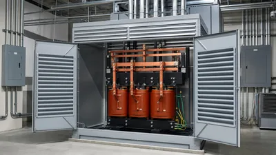
The service transformer for a 480Y/277 V building is usually a utility-owned or customer-owned three-phase pad-mounted unit, or a unit substation for larger loads. Secondary full-load current is I = kVA × 1,000 / (√3 × 480).
| kVA | 480 V full-load current | Typical main breaker |
|---|---|---|
| 300 | 361 A | 400 A |
| 500 | 601 A | 800 A |
| 750 | 902 A | 1,200 A |
| 1,000 | 1,203 A | 1,600 A |
| 1,500 | 1,804 A | 2,000 A |
| 2,000 | 2,406 A | 3,000 A |
| 2,500 | 3,007 A | 3,000 to 4,000 A |
Main breaker sizes are indicative; final selection follows NEC 240 and 450 rules, utility requirements and the service load calculation. Transformer impedance, typically 5.75 percent for 1,500 kVA units, sets the available fault current: 1,804 / 0.0575 = 31.4 kA with an infinite primary source, before motor contribution. Switchgear must be rated for this. The 480Y/277 V transformer itself is covered in the 480/277 transformer guide.
Next Steps: Specifying and Sourcing 480Y/277 V Equipment
A good RFQ for a 480Y/277 V service transformer or substation includes:
- kVA rating, primary voltage (for example 12,470 V or 13,200 V), connection and BIL.
- Secondary 480Y/277 V, grounded wye, 60 Hz, and whether a high-resistance grounding package is required.
- Impedance and the downstream switchgear short-circuit rating it must coordinate with.
- Radial or loop feed, bushing type, fusing and any utility standards to follow.
- Standards: IEEE C57.12.00 and C57.12.34 for pad-mounts; IEC 61439 or UL/ANSI equivalents for associated LV switchboards.
MARS manufactures three-phase pad-mounted transformers with 480Y/277 V secondaries and MV and LV switchgear, with routine tests on every unit, FAT welcome and lead times typically 25 to 45 days. Send your single-line diagram via the quote request.
Frequently asked questions
What is 277/480V 3 phase?
277/480V 3 phase is a four-wire grounded wye system with 480 V between any two phase conductors and 277 V from each phase to neutral. It is the standard service for large US commercial and industrial buildings, with 480 V feeding motors and HVAC and 277 V feeding lighting circuits.
Why is 277 volts used for lighting?
277 V lighting circuits carry more than twice the power of 120 V circuits on the same wire size, so fewer circuits, panels and conduits are needed. A 20 A, 277 V circuit supplies about 4.4 kW of continuous lighting load, compared with 1.9 kW at 120 V, with much lower voltage drop.
Is 277V single-phase?
Yes. A 277 V circuit uses one phase conductor and the neutral of a 480Y/277 V system, so it is single-phase. Three such circuits on phases A, B and C share the neutral. Single-phase 480 V loads can also be connected between any two phases of the same system.
How do you get 120V from 277/480V?
Install a step-down transformer. For panels, a three-phase dry-type transformer with 480 V delta primary and 208Y/120 V secondary is standard. For a few small loads, a single-phase 277 V to 120 V or 480 V to 120/240 V transformer can be used. The secondary must be grounded as a separately derived system.
What is the voltage from phase to ground on a 480V system?
On a solidly grounded 480Y/277 V wye, each phase is 277 V to ground. On an ungrounded or high-resistance grounded 480 V system, phase-to-ground voltage is nominally 277 V under normal conditions but can rise toward 480 V on the unfaulted phases during a ground fault.
What size transformer is needed for a 480/277 service?
Size the transformer from the service load calculation plus growth margin. Full-load current at 480 V is kVA x 1,000 divided by 831, so 500 kVA gives 601 A, 1,000 kVA gives 1,203 A and 2,500 kVA gives 3,007 A. Utilities may set sizes for services they own.
Written and reviewed by the MARS application engineering team in Shanghai, who specify and test transformers, switchgear, substations and battery storage for projects in 40+ countries. Last updated .
Tags: 277/480v 3 phase 480 277 voltage single phase 277 277 three phase 277 480v three phase