Key takeaways
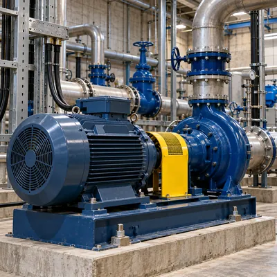
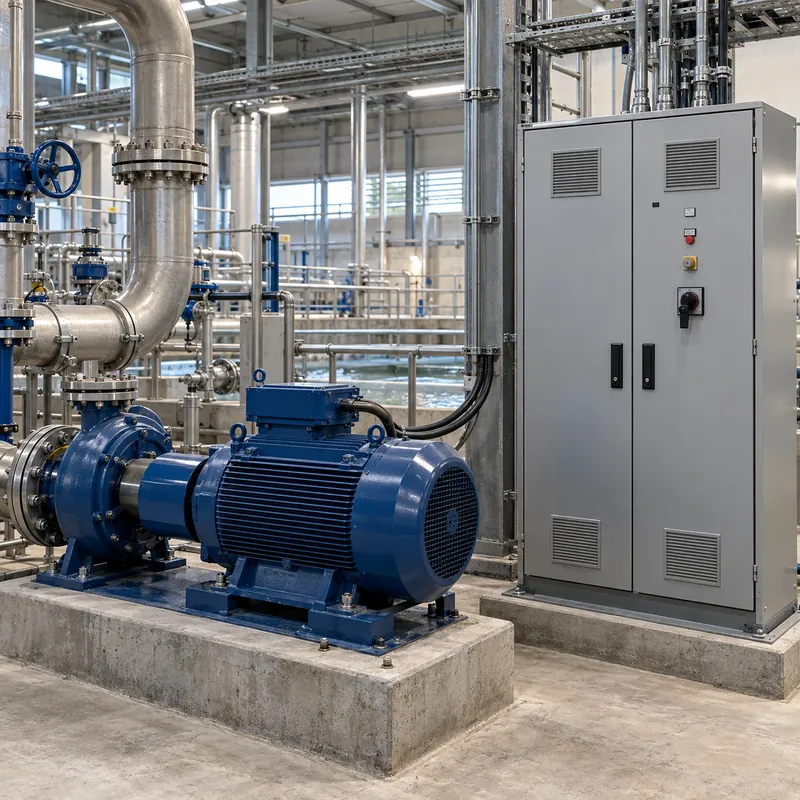
- Motor nameplates use utilization voltages of 200, 230, 460 and 575 V for 208, 240, 480 and 600 V nominal systems, allowing for distribution voltage drop.
- NEMA MG 1 permits operation at plus or minus 10 percent of rated voltage, so a 460 V motor is acceptable from 414 V to 506 V at rated frequency.
- Voltage unbalance of only 2 percent raises motor winding temperature rise by about 8 percent, and NEMA MG 1 recommends derating above 1 percent unbalance.
- A 120/240 V four-wire delta system supplies 240 V three-phase, 120 V single-phase from two legs, and 208 V from the high leg to neutral.
- NEC 110.15 requires the high leg of a four-wire delta to be marked orange, and NEC 408.3(E) places it on the B phase position in panelboards.
Quick answer: 460V 3 phase is the nameplate (utilization) voltage of motors and equipment designed for a 480 V three-phase system. The 20 V difference allows for voltage drop in the building. NEMA MG 1 lets a 460 V motor run from 414 to 506 V. The same convention gives 230 V motors for 240 V systems, including 120/240 V delta services with a 208 V high leg.
460 V is one of the most common numbers on North American motor nameplates, yet no utility delivers 460 V. The figure is a utilization voltage, deliberately set below the 480 V system nominal so the motor performs as designed after feeder drop. Understanding that relationship, and its counterparts at 230 V and 200 V, is key to matching motors, drives and transformers correctly.
This guide explains 460 V three-phase systems, voltage tolerance and unbalance, applying 460 V 60 Hz equipment abroad, and the related 240 V and 120/240 V delta systems where the high leg (transformer leg) appears. It is for plant engineers, OEMs, panel builders and buyers sourcing motors or supply transformers.
What Is 460V 3 Phase? Nominal vs Utilization Voltage
460 V three-phase is a rated utilization voltage, the voltage that equipment is designed to operate at, for use on a 480 V nominal system. ANSI C84.1 distinguishes system nominal voltage (what the utility and transformer provide) from utilization voltage (what arrives at equipment terminals after drop in feeders and branch circuits).
| System nominal | Motor nameplate | Ratio | Common system |
|---|---|---|---|
| 208 V | 200 V | 0.96 | 208Y/120 V |
| 240 V | 230 V | 0.96 | 240 V delta, 120/240 V delta |
| 480 V | 460 V | 0.96 | 480Y/277 V, 480 V delta |
| 600 V | 575 V | 0.96 | 600Y/347 V (Canada) |
| 4,160 V | 4,000 V | 0.96 | 4.16 kV industrial |
Each nameplate is about 4 percent below nominal. A 460 V motor fed from a 480 V transformer through a feeder with 3 percent drop receives about 466 V, slightly above nameplate and well within tolerance.
Many motors are dual-voltage 230/460 V, with nine or twelve leads reconnected for low or high voltage. On the high-voltage connection, winding sections are in series; on the low-voltage connection, in parallel. Current on 230 V is twice that on 460 V for the same output. Lead connection diagrams appear in 3-phase wiring for motors.
When people search 460 volts three phase, they usually mean a 480 V system. The system itself, including wye and delta forms, is covered in the 277/480V 3-phase system guide.
NEMA MG 1 Voltage Tolerance for 460 V Motors
NEMA MG 1 requires motors to run successfully at rated load with voltage within ±10 percent of rated, frequency within ±5 percent, and a combined variation not exceeding 10 percent. For a 460 V motor:
- Minimum voltage:
460 × 0.9 = 414 V - Maximum voltage:
460 × 1.1 = 506 V
Running within tolerance does not mean performance is unchanged. Approximate effects for a standard induction motor:
| Characteristic | At 90 percent voltage (414 V) | At 110 percent voltage (506 V) |
|---|---|---|
| Starting and maximum torque | About 81 percent (varies with V²) | About 121 percent |
| Full-load current | Increases roughly 10 percent | Decreases slightly, may rise on some designs |
| Full-load speed | Slight decrease (more slip) | Slight increase |
| Power factor | Slight increase | Decrease (more magnetizing current) |
| Temperature rise | Increases | Often decreases at load, increases at light load |
Practical guidance: aim to deliver 460 to 490 V at motor terminals under normal load. Undervoltage is generally more harmful than modest overvoltage because it raises current and heating. Transformer taps, typically ±2 × 2.5 percent on the primary, set the secondary level; select the tap after measuring voltage under load at commissioning.
A 50 hp, 460 V motor draws 65 A per NEC Table 430.250, about 52 kVA. Conversions between hp, kW and kVA for motor supply sizing are in the hp to kVA conversion guide.
Voltage Unbalance on 460 V Three-Phase Supplies
Voltage unbalance causes disproportionate heating in three-phase motors because it creates negative-sequence current that opposes rotation. NEMA MG 1 defines percent unbalance as:
% unbalance = 100 × (maximum deviation from average) / (average voltage)
- Measure the three line-to-line voltages at the motor terminals under load.
- Calculate the average of the three readings.
- Find the largest difference between any single reading and the average.
- Divide by the average and multiply by 100.
- Apply the NEMA derating factor if unbalance exceeds 1 percent, and investigate causes above 2 percent.
Worked example: readings of 462 V, 470 V and 455 V average 462.3 V. The largest deviation is 7.7 V (at 470 V; the 455 V reading deviates 7.3 V). Unbalance is 100 × 7.7 / 462.3 = 1.66 percent. The rule of thumb that temperature rise increases by about 2 × (% unbalance)² percent gives 2 × 1.66² = 5.5 percent extra heating. The NEMA MG 1 derating curve suggests operating at roughly 97 percent of rated load.
| Voltage unbalance | Approximate derating factor (NEMA MG 1 curve) |
|---|---|
| 1 percent | 1.00 |
| 2 percent | 0.95 |
| 3 percent | 0.88 |
| 4 percent | 0.82 |
| 5 percent | 0.75 |
Common causes include unevenly distributed single-phase 277 V loads, an open-delta transformer bank, a failing capacitor in a correction bank or a high-resistance connection. Field testing of motors, including unbalance diagnosis, is described in the 3-phase motor testing guide.
Can a 460 V 60 Hz Motor Run on 400 V 50 Hz?
Machinery built for North America often ends up in 50 Hz countries. The governing quantity is volts per hertz, which sets magnetic flux in the motor core.
- 460 V, 60 Hz:
460 / 60 = 7.67 V/Hz - 400 V, 50 Hz:
400 / 50 = 8.0 V/Hz, about 4 percent higher flux - 380 V, 50 Hz:
380 / 50 = 7.6 V/Hz, essentially matched
A 460 V 60 Hz motor on a 380 V 50 Hz supply runs with the same flux at five-sixths of its rated speed. Output power falls roughly in proportion, to about 83 percent of nameplate at rated torque. On 400 V 50 Hz the flux is slightly high, magnetizing current rises, and many motors tolerate it, but the manufacturer should confirm. On 415 V 50 Hz the V/Hz ratio is 8.3, 8 percent high, which is more likely to cause overheating.
Driven equipment must also be checked: pumps and fans deliver less flow at five-sixths speed, with head falling by the square of speed and power by the cube. Variable frequency drives eliminate the problem by producing 60 Hz output from a 50 Hz supply, provided the drive input is rated for local voltage.
Frequency effects on transformers are the mirror image, covered in the 50 Hz vs 60 Hz guide. Where an imported line needs 480 V at 60 Hz, a frequency converter is required; a transformer alone changes voltage only.
240 Volt 3 Phase and the 120/240 V Delta System
Below 480 V, the main three-phase alternatives for motor loads in older North American facilities are 240 V delta systems, with motors nameplated 230 V.
240 V three-wire delta
Three phase conductors at 240 V line-to-line, either ungrounded or corner-grounded. There is no neutral and no 120 V available from the system itself.
120/240 V four-wire delta (high-leg delta)
One of the three transformer windings has a grounded center tap. This produces:
- 240 V between any two phase conductors, for three-phase motors.
- 120 V from phases A and C to neutral, for lighting and receptacles.
- 208 V from phase B to neutral, the high leg or wild leg.
The high leg voltage is the height of an equilateral triangle with 240 V sides measured from the midpoint of one side: 240 × √3 / 2 = 207.8 V. This leg must never supply 120 V loads. NEC 110.15 requires it to be marked orange, and NEC 408.3(E) requires it in the B phase position of panelboards. Metering equipment may place it differently, so always verify by measurement.
Searches for 120 V three-phase or 120 240 three phase usually refer to this system, or to 208Y/120 V where 120 V is the phase voltage. There is no standard three-phase system with 120 V line-to-line. Construction of the high-leg delta transformer bank is explained in the 3-phase high-leg delta transformer guide, and the 208 V alternative in 208 vs 240 volts.
What Is a Transformer Leg? High Leg, Wild Leg and Open Delta
In everyday field language, a transformer leg means one phase winding of a transformer or bank, or the conductor fed from it. In a delta bank, the term high leg (also stinger or wild leg) identifies the phase with elevated voltage to neutral.
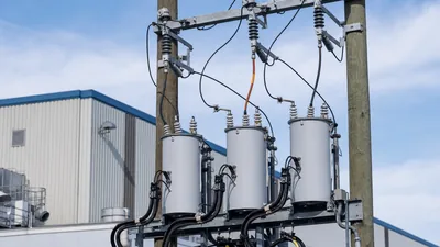
Many 120/240 V delta services are built from two or three single-phase pole-mounted transformers:
- Closed delta: three single-phase units. The lighting transformer (center-tapped) is typically larger, for example 50 kVA, with two 25 kVA power units.
- Open delta: two single-phase units, one center-tapped. Capacity is only 57.7 percent of a closed-delta bank of three equal units: two 25 kVA units supply
2 × 25 × 0.866 = 43.3 kVAof balanced three-phase load, not 50 kVA.
| Bank | Units | Three-phase capacity | Typical use |
|---|---|---|---|
| Closed delta, 3 × 25 kVA | 3 | 75 kVA | Small shop, mixed load |
| Open delta, 2 × 25 kVA | 2 | 43.3 kVA | Light three-phase load, farm |
| Lighting 50 kVA + 2 × 25 kVA | 3 | About 75 kVA three-phase plus lighting margin | Shop with heavy 120 V load |
Open-delta banks also produce voltage unbalance under load, which ties back to motor derating above. Measuring line-to-line voltages is explained in the three-phase line-to-line voltage guide.
Selecting the Supply Transformer for 460 V Motor Loads
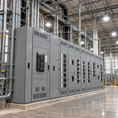
For a plant whose loads are mainly 460 V motors, the supply transformer secondary is 480 V, either 480Y/277 V (if 277 V lighting or ground-fault detection with a grounded neutral is wanted) or 480 V delta or high-resistance grounded wye (if continuity after a first ground fault matters).
- Total running kVA of all motors and other loads, using NEC full-load currents or nameplate data.
- Check the starting kVA of the largest motor and the resulting voltage dip, keeping motor terminals above about 85 percent of rated voltage during start.
- Choose kVA with growth margin and standard sizes such as 500, 750, 1,000, 1,500 or 2,000 kVA.
- Specify impedance to balance voltage dip against fault current.
- Specify primary taps to center the delivered voltage at 470 to 480 V under typical load.
Example: a plant has 820 kVA of running load including a 200 hp motor. A 1,000 kVA oil-immersed transformer at 5.75 percent impedance gives secondary current of 1,203 A and an infinite-bus fault current of about 20.9 kA. Starting the 200 hp code G motor (about 1,190 kVA locked-rotor) gives a dip of roughly 1,190 / (1,190 + 17,391) = 6.4 percent, acceptable for most processes. Selection details for this voltage class are in the 480V transformer selection and sizing guide.
Next Steps: Specifying and Sourcing 480 V Supply for 460 V Equipment
When requesting a transformer or substation for 460 V motor loads, include:
- Primary voltage and BIL, secondary 480Y/277 V or 480 V delta, 60 Hz, and the grounding method.
- kVA, impedance, primary taps and cooling class (ONAN, ONAF for oil-immersed; AN, AF for dry-type).
- Largest motor rating, starting method and acceptable voltage dip.
- Fault level available from the utility and downstream switchgear ratings.
- Standards: IEEE C57.12.00 or IEC 60076 with ANSI variants as required.
MARS manufactures oil-immersed transformers and pad-mounted transformers with 480 V secondaries for 60 Hz service, plus distribution and power transformers to 31,500 kVA, all routine tested with FAT welcome. Use the transformer sizing calculator for a first estimate and send your motor list through the quote request.
Frequently asked questions
Is 460V the same as 480V?
They refer to the same system. 480 V is the nominal system voltage supplied by the transformer, while 460 V is the utilization voltage on motor nameplates, set about 4 percent lower to allow for voltage drop in feeders. A 460 V motor is designed to run on a 480 V system.
What is the acceptable voltage range for a 460V motor?
NEMA MG 1 allows a 460 V motor to operate at rated load from 414 V to 506 V, which is plus or minus 10 percent of nameplate. Performance changes within that range: torque falls with the square of voltage, so at 414 V starting torque is about 81 percent of rated.
Can you get 120V from 240V three-phase?
Only from a four-wire high-leg delta system, where one transformer winding is center-tapped. Phases A and C each give 120 V to neutral, while phase B, the high leg, gives about 208 V to neutral and must not feed 120 V loads. A three-wire 240 V delta needs a separate transformer.
What is the high leg on a 3-phase transformer?
The high leg is the phase conductor in a 120/240 V four-wire delta system that measures about 208 V to neutral instead of 120 V. It results from center-tapping only one of the three delta windings. NEC 110.15 requires it to be marked orange, and it occupies the B phase position in panelboards.
Is there 120V three-phase power?
No standard system has 120 V between phases. The term usually refers to 208Y/120 V, where each phase is 120 V to neutral and 208 V line-to-line, or to 120/240 V high-leg delta. Both provide 120 V single-phase circuits alongside three-phase power at 208 V or 240 V.
Can a 460V motor run on 400V 50Hz?
Often yes, with reduced speed and output. The volts-per-hertz ratio at 400 V 50 Hz is 8.0, about 4 percent higher than the motor's 7.67 at 460 V 60 Hz, so flux rises slightly. The motor runs at five-sixths speed. Confirm with the manufacturer or use a variable frequency drive.
Written and reviewed by the MARS application engineering team in Shanghai, who specify and test transformers, switchgear, substations and battery storage for projects in 40+ countries. Last updated .
Tags: 460v 3 phase 460 volt 3 phase 120 240v 3 phase 240 volt 3 phase transformer leg