Key takeaways
- Three phase line to line voltage measures the potential difference between any two live phase conductors in a polyphase system.
- In a balanced wye (star) configuration, line to line voltage equals line-to-neutral voltage multiplied by the square root of three (approximately 1.732).
- In a delta configuration, the line to line voltage is identical to the individual phase winding voltage.
- Standard low-voltage ratings vary globally, predominantly 400 V at 50 Hz under IEC 60038 and 480 V or 208 V at 60 Hz under IEEE/ANSI standards.
- A line voltage imbalance of merely 2% can cause up to a 16% temperature rise in three-phase induction motors according to NEMA MG 1-2014.
Quick answer: Three phase line to line voltage is the root-mean-square (RMS) electrical potential measured between any two phase conductors in a three-phase alternating current system. In a balanced wye (star) distribution network, this potential equals the line-to-neutral voltage multiplied by the square root of three (√3 ≈ 1.732), whereas in a delta network, it directly equals the winding phase voltage.
In industrial electrical engineering and substation design, specifying the correct three phase line to line voltage determines conductor cross-sections, switchgear ratings, basic lightning impulse insulation levels (BIL), and transformer winding configurations. Power distribution networks rely on multi-phase delivery to transmit bulk electrical energy with lower conductor material volume compared to equivalent single-phase layouts. Whether commissioning an oil-immersed distribution transformer or engineering motor control centres, understanding how line potential behaves across star and delta topologies is essential for system stability, protective relay coordination, and equipment longevity.
Mathematical Relationship Between Line to Line and Line to Neutral Voltage
The mathematical relationship between line to line and line to neutral voltage in a balanced three-phase star system is governed by a fixed 30-degree phasor displacement and a magnitude scalar of √3.
In a balanced star-connected supply, the three phase-to-neutral voltages (often designated VAN, VBN, and VCN) share an identical RMS magnitude (VLN) but remain displaced from one another by 120 electrical degrees:
- VAN = VLN ∠ 0°
- VBN = VLN ∠ -120°
- VCN = VLN ∠ 120°
The potential between phase line A and phase line B, known as the line line voltage (VAB), represents the vector difference between their respective line-to-neutral potentials: VAB = VAN - VBN. Expressing this in complex rectangular form:
VAN = VLN(1 + j0)
VBN = VLN(-0.5 - j0.866)
VAB = VLN[(1 - (-0.5)) + j(0 - (-0.866))] = VLN(1.5 + j0.866)
Calculating the polar magnitude gives |VAB| = VLN × √(1.5² + 0.866²) = VLN × √(2.25 + 0.75) = VLN × √3 ≈ 1.73205 × VLN. The resultant phasor angle sits at +30° relative to VAN. Therefore, when an engineer measures 230 V from line to neutral on a standard European low-voltage network, the resulting 3 phase line to line voltage is 230 V × 1.732 = 398.36 V (nominally standardised as 400 V under IEC 60038 Table 1).
Three Phase Line to Line Voltage vs Line to Neutral in Star and Delta Systems
The core structural distinction between star (wye) and delta connections lies in how individual phase windings interface with incoming or outgoing transmission conductors.
In a delta connection, the transformer secondary windings form a closed loop. Because each transmission line taps directly into the junction between two adjacent windings, the line to line potential equals the phase winding potential:
- VLL = Vphase
- Iline = √3 × Iphase (under balanced operating conditions)
Delta systems do not inherently provide an accessible neutral point. When single-phase operational loads require connection, engineers must deploy a grounding transformer or utilise a 3 phase 4 wire system derived from a wye secondary winding. In a four-wire wye configuration, two distinct operational potentials are available simultaneously: the lower line-to-neutral potential for single-phase lighting and control circuitry, and the higher three phase line to line voltage for motors, heavy industrial heaters, and variable speed drives.
In commercial facilities operating on a North American 120/208 V service, matching the winding architecture to the load is vital. For deeper technical considerations on this service level, see our guide on 208V 3 phase power, which details how wye-connected distribution supplies both 120 V plug circuits and 208 V motor loads from a single transformer enclosure.
Standard Global Three Phase Line to Line Voltage Ratings
Standard three phase line to line voltage levels are codified by regional standards organisations to ensure equipment interoperability, grid synchronisation, and insulation coordination.
IEC 60038 establishes standardised voltages for 50 Hz networks across Europe, Africa, Asia, and Australasia, whereas IEEE C57.12.00 and ANSI C84.1 define voltage classes across North America and select Latin American markets operating at 60 Hz. The following table contrasts common low-voltage (LV) and medium-voltage (MV) nominal line-to-line ratings alongside their associated circuit topologies.
| Nominal Line to Line Voltage (VLL) | Nominal Line to Neutral (VLN) | Nominal Frequency (Hz) | Governing Standard | Typical Industrial Application |
|---|---|---|---|---|
| 208 V | 120 V | 60 Hz | ANSI C84.1 / IEEE C57 | Commercial buildings, light manufacturing, data centres |
| 400 V | 230 V | 50 Hz | IEC 60038 Table 1 | Global standard LV industrial, process facilities |
| 415 V | 240 V | 50 Hz | BS 7671 / AS 60038 | UK, Australian, and legacy Commonwealth plant distribution |
| 480 V | 277 V | 60 Hz | ANSI C84.1 Class B | North American heavy manufacturing, HVAC chillers |
| 690 V | 400 V | 50 Hz | IEC 60038 Table 1 | Wind turbine generation, marine propulsion, mining drives |
| 3,300 V (3.3 kV) | 1,905 V | 50/60 Hz | IEC 60038 / IEEE | Medium-voltage induction motors, underground mining pumps |
| 11,000 V (11 kV) | 6,350 V | 50 Hz | IEC 60038 Table 3 | Municipal distribution, industrial secondary substations |
| 13,800 V (13.8 kV) | 7,967 V | 60 Hz | IEEE C57.12.00 Table 5 | Industrial plant primary distribution, generation busbars |
| 33,000 V (33 kV) | 19,052 V | 50 Hz | IEC 60038 Table 3 | Sub-transmission, large solar and wind farm collectors |
| 34,500 V (34.5 kV) | 19,918 V | 60 Hz | ANSI C84.1 Table 2 | Utility renewable collector systems, primary distribution |
Selecting between these voltage levels impacts equipment sizing. For facilities operating under North American industrial utility supplies, review our comprehensive review of 480V 3 phase power to evaluate cable sizing and protection schemes.
Worked Sizing Calculation: Apparent Power and Line Current
Calculating line current from three phase line to line voltage and total apparent power enables engineers to accurately size circuit breakers, conductors, and transformer winding capacities.
Total apparent power (S) in a balanced three-phase AC system is defined by the three-phase power formula:
S = √3 × VLL × IL
Where S represents apparent power in volt-amperes (VA), VLL is the RMS 3 phase line to line voltage in volts (V), and IL is the line current in amperes (A). Rearranging for line current yields:
IL = S / (√3 × VLL)
Consider an engineering procurement package requiring a 1,000 kVA (1,000,000 VA) distribution transformer stepping medium-voltage down to feed an industrial motor control centre. We calculate the secondary full-load line current under two different standard supply regimes:
- Case A: Standard IEC 400 V System (50 Hz)
VLL = 400 V
IL = 1,000,000 / (√3 × 400) = 1,000,000 / 692.82 = 1,443.38 A
Phase-to-neutral voltage VLN = 400 / 1.73205 = 230.94 V - Case B: Standard ANSI 480 V System (60 Hz)
VLL = 480 V
IL = 1,000,000 / (√3 × 480) = 1,000,000 / 831.38 = 1,202.81 A
Phase-to-neutral voltage VLN = 480 / 1.73205 = 277.13 V
Operating at a higher three phase line to line voltage directly reduces full-load line current by 240.57 A (a 16.67% reduction). This difference permits smaller conductor cross-sections, reduced copper losses (I²R), and more compact low-voltage switchboards. For automated sizing checks across diverse kVA ratings, apply our practical 3 phase calculator.
Measuring and Testing Three Phase Line to Line Voltage on Transformers
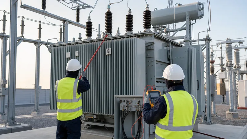
Measuring three phase line to line voltage across transformer bushings verifies ratio compliance, vector group phase displacement, and off-load tap positions during factory acceptance testing and site commissioning.
Under IEC 60076-1 clause 10.3 and IEEE C57.12.90 clause 7, voltage ratio verification confirms that the manufactured turns ratio corresponds directly to nameplate specifications within an allowable tolerance of ±0.5%. Field engineers follow this systematic sequence when performing voltage checks on a de-energised transformer using a three-phase ratio test set:
- Isolate all primary, secondary, and tertiary bushings from external busbars and verify de-energisation using an approved high-voltage proximity detector.
- Bond the transformer tank firmly to the substation earth grid to eliminate capacitive floating potentials.
- Attach the test leads from the ratio test set to the high-voltage bushings (terminals 1U, 1V, 1W or H1, H2, H3) and low-voltage bushings (2U, 2V, 2W or X1, X2, X3).
- Inject a balanced three-phase test voltage (typically 380 V to 415 V line-to-line) across the high-voltage winding.
- Simultaneously record the measured line line voltage across terminals 2U-2V, 2V-2W, and 2W-2U on the low-voltage side.
- Calculate the actual transformation ratio: Ratio = VLL(HV) / VLL(LV).
- Repeat the measurement across all tap changer positions, logging whether the measured three phase line to line voltage tracks the design table monotonically without step inversion.
Impact of Line Line Voltage Imbalance on Industrial Equipment
A line line voltage imbalance produces severe negative-sequence currents in rotating AC machinery, leading to excessive thermal stress, localized core saturation, and insulation degradation.
According to the International Electrotechnical Commission standard IEC 61000-2-4 Class 2, the allowable voltage unbalance factor (VUF)—defined as the ratio of negative-sequence voltage to positive-sequence voltage—must not exceed 2% in public and industrial distribution systems. NEMA MG 1-2014 clause 14.36 outlines that an electric induction motor operating on an unbalanced three-phase supply experiences negative-sequence magnetic flux opposing rotor rotation. This parasitic flux induces high-frequency eddy currents in the rotor bars.
The relationship between voltage imbalance and motor temperature rise approximates the following empirical formula:
Percent Temperature Rise = 2 × (Percent Voltage Imbalance)²
Under this dynamic, a seemingly minor 3.5% line line voltage imbalance creates approximately a 24.5% surge in operating winding temperature. Because transformer and motor winding insulation life halves for every 8°C to 10°C sustained rise above rated thermal limits (governed by the Arrhenius reaction rate), uncontrolled unbalance causes premature dielectric breakdown. Unbalanced line voltages also introduce 120 Hz or 100 Hz second-harmonic ripple currents onto the DC link of variable frequency drives (VFDs), stressing the DC bus capacitor bank and tripping input rectifier bridge protections.
Next steps: specifying and sourcing
Specifying the exact secondary three phase line to line voltage, tap changer regulation range (±2 × 2.5%), vector group configuration (such as Dyn11 or Ynd11), and short-circuit impedance (%Z) ensures seamless integration with your plant switchgear and downstream distribution infrastructure. When preparing procurement specifications for an engineering, procurement, and construction (EPC) bid or substation upgrade, submit your project single-line diagram (SLD), ambient operating conditions, insulation thermal class, and primary distribution feeder parameters. Our engineering team designs and manufactures custom power transformers, heavy-duty oil-immersed distribution transformers, and cast resin dry-type transformers compliant with IEC 60076, IEEE C57, and ISO 9001 quality management benchmarks. Request an engineering evaluation or submit your technical schedule directly through our transformer quotation page.
Frequently asked questions
What is three phase line to line voltage?
Three phase line to line voltage is the potential difference measured between any two phase conductors in a three-phase power network. In a wye system, it equals 1.732 times the phase-to-neutral voltage, while in a delta system, it directly equals the winding phase voltage.
How do you calculate 3 phase line to line voltage from phase to neutral?
Multiply the line-to-neutral voltage by the square root of three (approximately 1.73205). For instance, a 230 V phase-to-neutral supply yields a line to line voltage of 230 V × 1.732 ≈ 400 V.
Is line to line voltage higher than line to neutral voltage?
Yes, in a star (wye) connected electrical system, line to line voltage is always 73.2% higher than line-to-neutral voltage. In a delta configuration, there is no system neutral, so line-to-line potential is the sole primary voltage available across the conductors.
Why is line line voltage used to rate three-phase transformers?
Line line voltage defines the operational insulation class, clearance distances, and switchgear ratings required between external phase terminals. Specifying transformers by line to line voltage ensures proper coordination with utility grids and industrial distribution switchboards.
What causes line to line voltage unbalance in distribution systems?
Voltage unbalance is primarily caused by unequal distribution of single-phase loads across the three phases, untransposed overhead transmission lines, blown capacitor bank fuses, or transformer winding faults. High unbalance introduces harmful negative-sequence currents into three-phase induction motors.
Tags: three phase line to line voltage 3 phase line to line voltage line line voltage transformer voltage


