Key takeaways
- Standard transformer wiring relies on standard terminal markings where H denotes high-voltage primary windings and X denotes low-voltage secondary windings under IEEE C57.12.70 and IEC 60076-1.
- Dual-voltage secondary windings wired in series double the terminal voltage, whereas parallel configurations double the rated current capacity while keeping output voltage constant.
- A standard 480 to 240 single-phase transformer hook up requires connecting primary leads H1 and H2 across 480 V line-to-line while placing low-voltage windings in series across both coils.
- Residential split-phase wiring delivers 120/240 V by establishing an earthed neutral at the secondary centre tap between terminals X2 and X3, complying with NEC Article 250 and IEC 60364.
- Before energising any transformer connection, field technicians must verify insulation resistance with a 1,000 V or 2,500 V DC Megohmmeter and confirm correct turns ratio and polarity.
Quick answer: Transformer wiring involves correctly landing primary supply conductors and secondary load conductors onto designated high-voltage (H) and low-voltage (X) terminals according to the unit's schematic diagram. Depending on whether windings are connected in series or parallel, the hook up determines operating voltages, current capacities, grounding schemes, and phase relationships.
Executing proper transformer wiring is fundamental to ensuring equipment safety, system efficiency, and code compliance in utility, industrial, and commercial electrical distribution. An incorrect terminal jumper or phase displacement will cause severe circulating currents, phase imbalance, or catastrophic insulation failure under fault conditions. Whether commissioning a low-voltage dry-type unit or an oil-filled distribution transformer, field engineers must understand polarity conventions, terminal designation standards, and dual-voltage winding arrangements. For complete background on foundational systems, review our 3-phase transformer guide and our reference on transformer electrical schematics and symbols.
Understanding Terminal Markings and Polarity in Transformer Wiring
Terminal markings and relative polarity define the phase relationship between primary and secondary windings during operation. Under IEEE C57.12.70 and IEC 60076-1, high-voltage terminals are designated by the letter H (such as H1, H2, H3), while low-voltage terminals are designated by X (such as X1, X2, X3, and neutral X0). By standard industry convention, terminal H1 and terminal X1 share the same instantaneous polarity; when alternating current flows into terminal H1, the induced current emerges simultaneously from terminal X1.
Transformer polarity is classified as either additive or subtractive. In subtractive polarity—mandated for all three-phase transformers and single-phase transformers rated above 200 kVA with primary voltages exceeding 8,660 V—terminal H1 is located directly opposite terminal X1 across the tank or enclosure. If an external jumper connects H1 to adjacent X1 and rated voltage is applied across the primary, the measured voltage between H2 and X2 equals the difference between primary and secondary voltages ($V_{\text{primary}} - V_{\text{secondary}}$). In additive polarity, typical of smaller single-phase utility distribution transformers under 200 kVA, terminal X1 is diagonally opposite terminal H1, meaning test voltage measured between the remaining terminals reflects the sum of both windings ($V_{\text{primary}} + V_{\text{secondary}}$). Verifying polarity is an essential precursor to parallel operation or complex polyphase banking.
Single Phase Transformer Wiring Diagram and Dual-Voltage Configurations
A standard single phase transformer wiring diagram illustrates how multiple winding coils inside the core-and-coil assembly can be interconnected to achieve different operating voltages. Most industrial dry-type control and distribution transformers feature dual primary windings (rated 240/480 V) and dual secondary windings (rated 120/240 V), providing four discrete input/output combinations using copper busbar links or factory jumper cables.
When completing single phase transformer wiring for dual-voltage coils, engineers apply two basic rules: series connections sum the voltages, while parallel connections sum the current capacities. When wiring dual primary coils (the first and second primary windings) for high-voltage supply (e.g., 480 V), terminal H2 is tied to terminal H3, and line power is landed on H1 and H4. For a low-voltage supply (e.g., 240 V), H1 is linked to H3, and H2 is linked to H4, effectively placing the primary coils in parallel. The identical logic governs the secondary winding connections across both coils:
- Series Secondary Connection (High Voltage): Link terminal X2 to X3. Load conductors land on X1 and X4. The available secondary voltage is 240 V at the full kVA rating.
- Parallel Secondary Connection (Low Voltage): Link terminal X1 to X3, and link terminal X2 to X4. Load conductors land on the paralleled secondary terminals. The available secondary voltage is 120 V with double the rated secondary current ($I = \text{kVA} / 0.120\text{ kV}$).
Consulting the exact single phase transformer diagram on the manufacturer nameplate before torquing connections prevents cross-winding short circuits caused by accidental out-of-phase links.
480 to 240 Single Phase Transformer Wiring Diagram and Industrial Hook Up
An industrial 480 to 240 single phase transformer wiring diagram represents the standard step-down configuration used to supply 240 V single-phase machinery, commercial ovens, or subpanels from a 480 V three-phase distribution system. In this arrangement, two ungrounded phase legs (e.g., Line A and Line B) from a 480 V switchboard feed the primary side of the transformer, providing 480 V phase-to-phase potential.
To execute this specific transformer hook up, wire the terminals as follows:
- Land primary Phase A onto terminal H1 and primary Phase B onto terminal H4.
- Install a heavy-duty factory copper jumper bar between primary terminals H2 and H3 to place the primary coils in series for 480 V operation.
- Install a jumper link between secondary terminals X2 and X3 to put the two 120 V low-voltage windings in series, producing 240 V across the outer terminals.
- Connect the downstream single-phase feeder conductors directly to secondary terminals X1 and X4.
- If local regulations (such as NEC 250.20(B) or IEC equivalents) permit an isolated or impedance-earthed 240 V circuit, bond the enclosure to the equipment grounding conductor (EGC) without grounding secondary conductors; if grounding is required, follow the appropriate system grounding guidelines.
Before commissioning the installation, always confirm insulation integrity between winding groups using the methods outlined in our guide on checking insulation resistance.
Residential Transformer Diagram: Split-Phase 120/240V Hook Up
A typical residential transformer diagram outlines a single-phase three-wire split-phase secondary system, which provides both 120 V for domestic branch circuits and 240 V for heavy loads like HVAC compressors and water heaters. This system is typically fed by a medium-voltage primary line (such as 7.2 kV or 13.8 kV phase-to-ground) via an overhead or pad-mounted unit.
The secondary side utilizes two series-connected 120 V secondary coils. The physical connection between terminal X2 and terminal X3 acts as the winding's center tap. This center tap is brought out to a dedicated terminal, designated as the neutral terminal ($N$ or $X_0$). The complete hook up features:
- Line 1 (L1): Originates at terminal X1, providing 120 V AC relative to the neutral conductor.
- Neutral (N): Originates at the center tap (secondary coil bond) and is bonded to earth via a grounding electrode conductor (GEC) at the main service panel, establishing a reference potential of 0 V.
- Line 2 (L2): Originates at terminal X4, providing 120 V AC relative to neutral and operating 180 electrical degrees out of phase with L1.
- Line-to-Line Potential: Connecting across L1 (X1) and L2 (X4) delivers 240 V AC for high-current industrial or domestic equipment.
Proper sizing of the neutral conductor and solid bonding to the earthing electrode prevent dangerous neutral floating voltages during unbalanced domestic loading conditions.
Three-Phase Transformer Wiring: Delta and Wye Terminal Connections
Three-phase transformer wiring interconnects three separate single-phase winding sets—or a single three-phase laminated core assembly—into Delta ($\Delta$) or Wye (Y) configurations. These interconnections determine phase angle displacement, harmonic circulation, and fault current behavior. Common standard vector groups defined under IEC 60076 include Dyn11 and Ynd1, whereas ANSI/IEEE designs typically standardize on a 30-degree secondary phase lag relative to the primary.
In a Delta primary wiring configuration, the three primary phase legs are wired across the windings in an end-to-end loop: line terminal A connects to H1 of phase 1 and H2 of phase 3; line B connects to H1 of phase 2 and H2 of phase 1; and line C connects to H1 of phase 3 and H2 of phase 2. In a Wye secondary configuration, terminals X2 of all three phases are tied together to form a common neutral point ($X_0$), while terminals X1 serve as individual phase outputs ($A, B, C$). For in-depth schematics, vector diagrams, and calculations, see our detailed guide on the Delta-Wye transformer diagram.
Step-by-Step Transformer Wiring Guide: Safe Field Installation Procedure
This transformer wiring guide outlines the sequential field engineering procedure required to safely terminate, bond, and inspect dry-type or liquid-filled transformers in commercial and industrial settings.
- De-energise and Lockout: Isolate all primary and secondary power sources, apply Lockout/Tagout (LOTO) padlocks, test for zero voltage with a calibrated instrument, and earth the incoming cables using temporary grounding leads.
- Inspect and Clean: Open the terminal compartment, remove shipping blocks, clear debris or moisture, and verify that the nameplate kVA, primary voltage, and secondary voltage match site engineering drawings.
- Configure Internal Links: Install the series or parallel copper jumper bars on high-voltage and low-voltage tap boards according to the selected system voltage and tap switch position (±2.5% or ±5%).
- Pull and Train Conductors: Route primary and secondary power cables, maintaining minimum cable bending radiuses per manufacturer specifications. Avoid exerting mechanical tension or shear stress on porcelain or cast-resin terminal bushings.
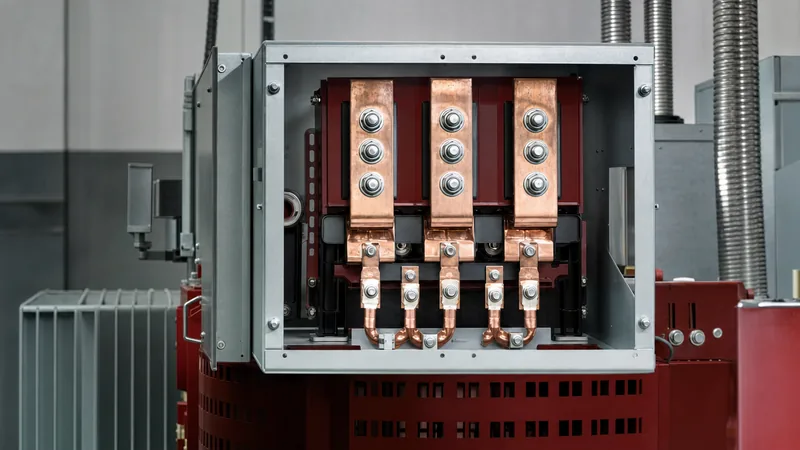
- Terminate Conductor Lugs: Crimp certified compression lugs onto conductor ends, wire-brush contact surfaces, apply non-conductive electrical joint compound to aluminium terminations, and bolt to terminals using Belleville spring washers.
- Torque Fasteners to Spec: Tighten all terminal bolts using a calibrated torque wrench. For standard Grade 5 high-tensile steel 1/2-inch (M12) bolts, apply between 45 and 55 N·m (33 to 40 ft-lb), marking each torqued bolt with torque seal.
- Establish System Grounding: Bond the transformer core, enclosure, and secondary neutral (if derived) to the main grounding grid using an adequately sized copper grounding electrode conductor in line with NEC 250 or IEC 60364.
- Perform Pre-Energisation Tests: Complete an insulation resistance test (insulation tester) at 1,000 V or 2,500 V DC, verify winding continuity, check primary-to-secondary turns ratios, and clear all personnel before closing the breaker.
Transformer Wiring Comparison and Terminal Connection Guide
The connection matrix below details standard low-voltage distribution transformer wiring combinations, terminal designations, jumper arrangements, and grounding practices across single-phase and three-phase topologies.
| Configuration | Input Voltage (V) | Output Voltage (V) | Primary Jumpers | Secondary Jumpers | Grounding / Neutral Point |
|---|---|---|---|---|---|
| 1-Phase Dual-Voltage (Series-Series) | 480 V (1-Ph) | 240 V (1-Ph) | H2 to H3 | X2 to X3 | Enclosure ground only (floating) |
| 1-Phase Split-Phase (Series-Series) | 480 V (1-Ph) | 120/240 V (3-Wire) | H2 to H3 | X2 to X3 | secondary center-tap junction bonded to neutral/ground |
| 1-Phase Parallel-Parallel | 240 V (1-Ph) | 120 V (1-Ph) | H1 to H3 & H2 to H4 | X1 to X3 & X2 to X4 | Secondary neutral conductor bonded to neutral/ground |
| 3-Phase Delta-Wye (Dyn11 / ANSI 30°) | 480 V (3-Ph) | 208Y/120 V (4-Wire) | Closed Delta loop | Common Wye point (X0) | X0 grounded to main electrode system |
| 3-Phase Delta-Delta | 480 V (3-Ph) | 240 V (3-Ph) | Closed Delta loop | Closed Delta loop | Corner grounded or ungrounded with detector |
| 3-Phase High-Leg Delta | 240 V (3-Ph) | 120/240/208 V | Closed Delta loop | Center tap on one phase coil | Secondary center tap grounded; high leg = 208 V to ground |
Ensure that all site installations respect system voltage tolerances (typically ±5% under nominal loading conditions) and comply with local fault clearing times specified by upstream protective devices.
Next steps: specifying and sourcing
When specifying custom or standard power transformers, delivering accurate wiring specifications to the factory guarantees seamless commissioning on site. Prepare your full system single-line diagram, nominal primary line voltage, desired secondary output configuration (including any requirement for dual-voltage or split-phase windings), vector group displacement, tap-changer ranges, BIL ratings, and enclosure protection ratings (IP or NEMA). Explore our extensive industrial portfolio of dry-type transformers, heavy-duty oil-immersed transformers, and compact pad-mounted transformers. Contact our application engineering team directly through our transformer quote page to request detailed submittal drawings, wiring schematics, and factory pricing.
Frequently asked questions
How do you wire a 480 to 120/240V single-phase transformer?
To wire a 480 to 120/240 V single-phase transformer, connect the 480 V supply lines to primary terminals H1 and H4, and place an internal jumper between H2 and H3. On the secondary side, link terminals X2 and X3 together to form the grounded neutral center tap, while landing the two 120 V ungrounded conductors onto terminals X1 and X4.
What is the difference between additive and subtractive transformer polarity?
In subtractive polarity, terminal H1 is directly adjacent to terminal X1, resulting in a test voltage equal to primary voltage minus secondary voltage when adjacent terminals are linked. In additive polarity, terminal X1 is diagonally opposite terminal H1, causing the measured voltage between unconnected terminals to be the sum of primary and secondary voltages.
What happens if secondary transformer jumpers are wired incorrectly?
Wiring secondary jumpers incorrectly can cause a dead short circuit across the secondary coils, triggering severe overcurrent, protective device tripping, or instant thermal failure of the insulation. An incorrect jumper configuration may also result in zero output voltage due to opposing magnetomotive forces or deliver an unexpected voltage that destroys connected loads.
Why is the secondary neutral grounded in a transformer wiring hook up?
The secondary neutral is grounded to stabilize line-to-ground voltages against static charge and lightning surges, prevent transient overvoltages, and provide a low-impedance return path for ground-fault current. This deliberate return path ensures upstream circuit breakers or fuses trip rapidly under single line-to-ground fault conditions.
How do you wire a dual-voltage transformer for low-voltage operation?
To configure dual primary coils for low-voltage operation, place the two windings in parallel by connecting terminal H1 to H3 and terminal H2 to H4 using manufacturer-approved jumper links. Incoming line voltage is then landed across the combined primary termination points.
Tags: transformer wiring transformer wiring diagram transformer hook up single phase transformer wiring transformer wiring guide


