Key takeaways
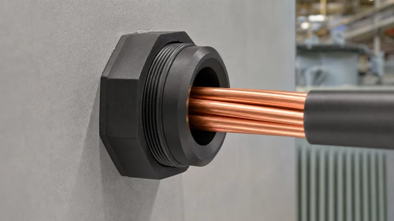
- A 2 plastic bushing provides critical mechanical edge protection and electrical insulation where secondary conductors enter metal enclosures or transformer terminal boxes.
- NEC Article 300.4(G) mandates an insulating bushing for conductors sized 4 AWG or larger entering enclosures through raceways of trade size 2 inches or larger.
- High-grade 2 inch plastic bushing components utilise glass-filled nylon 6/6 or polypropylene rated up to 105°C to 150°C with UL 94 V-0 flame-retardant certification.
- Secondary transformer polymeric bushings with a 2 in bushing shank diameter require precise installation torque (typically 18 to 22 Nm) to prevent gasket over-compression.
- Cable pull sidewall bearing pressure (SWBP) at 90-degree transitions makes a flared throat radius on every 2-inch insulating bushing essential to preserve conductor insulation integrity.
Quick answer: A 2 plastic bushing is a high-grade thermoplastic or polymeric insulating component designed either as a trade size 2-inch conduit insulating fitting or as a 2-inch secondary terminal interface. It protects power conductors from sharp enclosure edges, prevents phase-to-ground flashovers, and absorbs mechanical stress during dynamic cable loading in electrical distribution systems.
Low-voltage terminations within modern distribution equipment require uncompromising dielectric isolation and physical cable protection. When feeder cables enter low-voltage cable boxes, throats, or switchgear compartments from an oil-immersed transformer or a prefabricated substation, raceway edges present a severe shear risk to conductor insulation. Similarly, low-voltage secondary terminals frequently rely on robust polymeric mouldings to seal internal tank fluid and separate high-current busbars. Choosing and installing the correct 2 plastic bushing ensures regulatory compliance, minimises partial discharge risks, and prevents costly insulation breakdowns during full-load thermal cycling.
What Is a 2 Plastic Bushing in Electrical and Transformer Installations?
A 2 plastic bushing refers to an engineered non-conductive assembly manufactured for a 2-inch (50.8 mm nominal trade size or shank diameter) enclosure opening or terminal penetration. In electrical engineering practice, the phrase encompasses two distinct apparatus types: high-impact conduit-terminating insulating bushings and low-voltage transformer wall bushings.
The first type is a threaded or press-fit conduit insulating bushing designed to thread directly onto a 2-inch rigid metal conduit (RMC), intermediate metal conduit (IMC), or low-voltage entry hub. Standardised under UL 514B and BS EN 61386-1, this fitting creates a smooth, well-radiused throat that prevents mechanical abrasion of secondary cables as they enter transformer terminal compartments. The second apparatus type is a secondary low-voltage molded polymeric terminal, often termed a 2 in bushing, installed on distribution transformers to pass low-voltage copper or aluminium spade leads through the tank cover or sidewall while maintaining an airtight, fluid-tight seal. For high-voltage and primary-side configurations, contrast these fittings against porcelain and resin designs detailed in our Transformer Bushing Guide: Engineering, Types & Testing.
Material Properties and Temperature Ratings for 2 Inch Plastic Bushing Components
Molded polymeric bushings must withstand severe electrical, mechanical, and thermal stresses without cracking, creeping, or tracking. The raw materials used in the manufacture of a 2 inch plastic bushing determine its environmental resilience and operational lifespan.
Engineering thermoplastics utilised in these components fall into three primary categories:
- High-Impact Polypropylene (PP): Standard for indoor raceway terminations operating between -20°C and +90°C. Polypropylene offers cost-effective dielectric resistance (approximately 18 to 22 kV/mm) and high elasticity against dynamic cable vibration, though it exhibits lower dimensional stability under continuous mechanical load.
- Glass-Filled Polyamide (Nylon 6/6): Engineered for high-temperature switchgear cable boxes and transformer enclosures. Nylon 6/6 modified with 15% to 30% glass reinforcement provides a continuous operating temperature limit up to 130°C or 150°C, high tensile strength (>120 MPa), and an flammability classification of UL 94 V-0.
- Cycloaliphatic Epoxy / Polycarbonate Blends: Specifically formulated for fluid-contact secondary transformer penetrations, offering chemical resistance to mineral insulating oil, synthetic esters, and ambient ultraviolet (UV) radiation without dielectric degradation.
Specifiers must ensure that the continuous thermal index of the chosen material matches the temperature class of the cable insulation (typically 90°C for XLPE/EPR) and the winding temperature rise parameters defined under IEC 60076-2.
Mechanical and Electrical Specifications: 2 in Bushing Engineering Data
Engineering selection requires matching the mechanical dimensions, dielectric properties, and torque ratings of a 2 in bushing to the operating parameters of the connected circuit. The following comparative data delineates standard parameters for conduit-mount versus transformer tank-mount applications.
| Engineering Parameter | Conduit Insulating Bushing (Trade Size 2") | Transformer Secondary Bushing (2" Shank) |
|---|---|---|
| Nominal Conduit / Hole Size (mm) | 60.3 mm (2.375 in OD) | 50.8 mm to 54.0 mm hole cutout |
| Throat Internal Diameter (mm) | 49.5 mm to 52.0 mm | Conductor dependent (16 mm to 32 mm) |
| Dielectric Breakdown Strength (kV/mm) | 16 to 24 kV/mm | 28 to 35 kV/mm |
| Operating Temperature Range (°C) | -40°C to +105°C (Nylon up to 130°C) | -40°C to +120°C continuous |
| Flammability Rating | UL 94 V-0 or UL 94 V-2 | UL 94 V-0 self-extinguishing |
| Maximum Tightening Torque (Nm) | 9.5 to 14.0 Nm (threaded locknut) | 18.0 to 22.0 Nm (tank flange studs) |
| Impact Resistance (Joules at -20°C) | > 7.0 J (UL 514B drop ball test) | > 15.0 J (cantilever test) |
| Standard Reference | UL 514B / CSA C22.2 No. 18.3 | IEEE C57.12.00 / IEC 60137 |
These dimensional and performance boundaries prevent mechanical shear during short-circuit electromagnetic pulses while preventing moisture ingress into sensitive connection chambers.
Code Compliance and Safety Standards: NEC 300.4(G), UL 514B, and IEEE C57
Compliance with electrical safety standards is legally binding on industrial projects and essential for equipment acceptance. When power feeders traverse metal raceways, regulatory bodies explicitly specify the inclusion of protective insulating throats.
Under the US National Electrical Code (NEC / NFPA 70) Article 300.4(G), ungrounded conductors of trade size 4 AWG (21.2 mm²) or larger entering an enclosure, cabinet, or pull box through a raceway must be protected by a substantially rounded insulating surface. If a conduit enters an enclosure without a threaded boss, a threaded 2 plastic bushing made of insulating material—or a metal fitting with an integral plastic liner—must be fastened securely. Underwriters Laboratories standard UL 514B clause 8.3 requires these fittings to withstand rigorous pull-out, torque, and cold-impact testing without chipping or cracking.
On transformer tank covers, IEEE C57.12.34 and IEC 60076-1 mandate minimal electrical clearance through air and creepage distance over insulating surfaces. When deploying a bushing 2 inch configuration on a secondary spade terminal, engineers must verify that the creepage distance meets or exceeds 25 mm/kV for moderate pollution environments, avoiding surface flashovers under condensing relative humidity. For installations operating inside modular substations, these clearances correlate directly with structural spacing rules outlined in our Unit Substation Engineering Guide.
Step-by-Step Installation Procedure for Bushing 2 Inch Terminations
Installing a bushing 2 inch assembly correctly ensures dielectric integrity and mechanical stability throughout decades of vibration and thermal cycling. Electrical contractors must execute installation following a disciplined sequential protocol.
- Enclosure Preparation and Deburring: Punch or drill the 2-inch trade opening (60.3 mm nominal clearance for conduit; 51 to 54 mm for transformer wall units). Remove all metallic burrs, filings, and sharp edges using a deburring tool to prevent damage to the polymer body or sealing gaskets.
- Gasket and Seal Positioning: For transformer fluid seals or outdoor NEMA 3R/4 enclosures, fit a high-grade nitrile butadiene rubber (NBR) or fluoroelastomer (FKM) O-ring onto the outer shoulder of the bushing before inserting the fitting through the enclosure wall.
- Mechanical Fastening: Thread the polymeric retaining collar or metallic locknut onto the threaded shank. Tighten by hand until flush, then use a calibrated torque wrench with a non-marring socket to torque the assembly to the manufacturer's specified limit (typically 12 to 14 Nm for trade size 2 fittings). Do not exceed recommended values, as overtightening causes plastic thread deformation.
- Cable Pulling Preparation: Verify that the rounded interior throat radius of the 2-inch plastic fitting is unobstructed and free of manufacturing flash. Apply non-conductive cable pulling lubricant to both the cable jacket and the plastic throat prior to drawing heavy feeder cables.
- Final Conductor Inspection: Once conductors are pulled and terminated onto terminal lugs or spade connectors, perform a visual and tactile inspection to confirm the insulation jacket rests comfortably against the curved plastic radius without pinched stress points.
Adhering to these steps eliminates installation-induced micro-fractures, which are a leading cause of moisture ingress and insulation breakdown during plant operation, as discussed in our Industrial Power System Installation Guide.
Worked Engineering Calculation: Cable Sidewall Bearing Pressure and Bushing Sizing
Calculating the sidewall bearing pressure during feeder cable installation confirms whether a standard 2 inch plastic bushing provides adequate mechanical support or if a heavy-duty reinforced polymer collar is mandatory.
Consider an installation where three single-core 500 kcmil (253 mm²) copper XLPE cables are drawn through a 2-inch rigid conduit entering the low-voltage terminal compartment of a pad-mounted transformer. The conduit incorporates a 90-degree bend with a bend radius $R = 0.24\text{ m}$ immediately before the bushing termination.
Given Parameters:
- Total cable weight ($w$): $7.45\text{ kg/m}$ ($73.1\text{ N/m}$) across three conductors.
- Horizontal pull length ($L$): $40\text{ m}$.
- Coefficient of dynamic friction ($\mu$): $0.35$ (lubricated synthetic polymer).
- Radius of conduit bend ($R$): $0.24\text{ m}$.
Step 1: Calculate Pulling Tension ($T$) at the Entry of the Bend:
$$T_1 = \mu \times w \times L = 0.35 \times 73.1\text{ N/m} \times 40\text{ m} = 1,023.4\text{ N}$$
Step 2: Calculate Tension ($T_2$) Exiting the 90-Degree (\pi/2\text{ rad}) Bend:
$$T_2 = T_1 \times e^{\mu \times \theta} = 1,023.4 \times e^{0.35 \times 1.571} = 1,023.4 \times 1.733 = 1,773.6\text{ N}$$
Step 3: Calculate Cable Sidewall Bearing Pressure ($SWBP$):
For a cradle-mounted or triangular cable configuration passing over the throat of a 2 in bushing:
$$SWBP = \frac{T_2}{R} = \frac{1,773.6\text{ N}}{0.24\text{ m}} = 7,390\text{ N/m} \approx 506\text{ lbs/ft}$$
Standard XLPE cable insulation has an allowable continuous sidewall bearing pressure limit of approximately $7,300\text{ N/m}$ ($500\text{ lbs/ft}$) when pressed against a broad, curved surface, but its limit drops below $2,900\text{ N/m}$ ($200\text{ lbs/ft}$) if pulled across a sharp metallic edge. This calculation proves that an unbushed enclosure edge would irrevocably slice the cable sheath under $7,390\text{ N/m}$ of load. Installing a 2 plastic bushing with a smooth flared throat radius of at least $r \ge 3.2\text{ mm}$ distributes the contact area, reducing local contact stress to safe levels and ensuring cable integrity.
Next steps: specifying and sourcing
When specifying a 2 plastic bushing for distribution equipment or plant raceways, engineers must provide complete mechanical drawings, continuous operating temperature limits, flammability ratings, and chemical exposure parameters. Ensure your procurement package defines trade size compatibility, thread pitch (such as NPT or metric), and dielectric breakdown requirements. For tailored power distribution hardware, explore our specialised pad-mounted transformers, heavy-duty oil-immersed transformers, and engineered transformer substations. To request project-specific submittals or factory-direct volume pricing, visit our direct quote submission page or submit your technical schedule via our engineering contact page.
Frequently asked questions
Why is a 2 plastic bushing required on conduit entering a transformer enclosure?
A 2 plastic bushing is required by NEC Article 300.4(G) to prevent sharp raceway edges from cutting or abrading power conductor insulation. The rounded, insulating throat ensures that mechanical pulling tension and thermal expansion do not create ground faults or short circuits.
What is the difference between a 2 inch plastic bushing and a metallic insulated grounding bushing?
A 2 inch plastic bushing consists entirely of high-dielectric polymer designed solely for physical conductor protection and electrical isolation. A metallic insulated grounding bushing incorporates an aluminium or zinc body with a copper bonding lug to provide an equipment grounding path alongside a plastic throat liner.
What temperature rating should I specify for a 2 in bushing?
You should specify a 2 in bushing rated for at least 105°C for general commercial systems, or 130°C to 150°C (glass-filled nylon) for industrial switchgear and transformer compartments. The bushing temperature rating must match or exceed the temperature rating of the entering power cables.
Can a 2 plastic bushing be used outdoors in direct sunlight?
Yes, provided the polymer resin is formulated with UV-stabilising additives like carbon black or specialised hindered amine light stabilisers (HALS). Without UV stabilisers, standard outdoor plastic bushings degrade, turn brittle, and crack within two to three years of solar exposure.
How tight should a bushing 2 inch locknut be torqued during installation?
A bushing 2 inch fitting with standard polymeric threads should be torqued to between 9.5 Nm and 14.0 Nm. Overtightening past 16 Nm risks stripping the moulded plastic threads or cracking the locknut collar, compromising the enclosure seal.
Tags: 2 plastic bushing 2 inch plastic bushing 2 in bushing bushing 2 inch transformer bushings


