Key takeaways
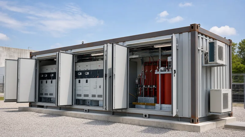
- A containerized electrical substation integrates MV switchgear, distribution transformer, and LV switchboards into a pre-commissioned, transportable ISO enclosure complying with IEC 62271-202.
- Internal arc classification (IAC-AB) within container enclosures requires pressure-relief blow-off flaps sized to exhaust overpressures exceeding 100 kPa within 10 to 15 milliseconds.
- Thermal sizing must accommodate transformer heat losses alongside solar radiation gains, typically requiring 3.0 to 4.5 cubic metres of forced airflow per minute per kilowatt of rejected heat.
- Factory acceptance testing allows up to 90 percent of commissioning tasks to be completed off-site, reducing on-site civil and electrical installation schedules from months to days.
- Structural integrity demands minimum 3 mm weathering steel framing with C4 or severe marine-grade anti-corrosion coatings to deliver a design life exceeding 25 years in harsh industrial or coastal environments.
Quick answer: A containerized electrical substation is a factory-engineered, transportable assembly that houses medium-voltage switchgear, step-up or step-down distribution transformers, low-voltage switchboards, and protection systems within a thermally insulated ISO-style enclosure. Built and tested to IEC 62271-202, it replaces site-built masonry substations to reduce civil lead times and project footprint.
Industrial utilities, renewable energy developers, and mining sites increasingly specify modular power distribution over conventional civil infrastructure. A container substation delivers fully integrated primary and secondary equipment on a pre-cast foundation or skid base. Because the enclosure integrates climate control, auxiliary battery systems, fire suppression, and SCADA monitoring before dispatch, field activities are largely restricted to external cable termination and final verification tests, closely matching the deployment strategy seen in a mobile substation engineering guide.
Containerized Electrical Substation Architecture and Layout
A containerized electrical substation comprises three segregated functional compartments: the medium-voltage (MV) room, the transformer bay, and the low-voltage (LV) and automation control room.
Separation barriers prevent fault propagation, maintain distinct thermal zones, and safeguard operational personnel. Under IEC 62271-202 (High-voltage/low-voltage prefabricated substation), internal partition walls must maintain structural integrity and thermal isolation between components during continuous operation and fault events:
- MV Switchgear Compartment: Accommodates ring main units (RMUs) or metal clad switchgear with ratings commonly spanning 11 kV to 36 kV. This compartment maintains dedicated operator aisles adhering to minimum clearance widths of 800 mm to 1000 mm for safe manual switching and breaker racking.
- Transformer Compartment: Designed for either cast-resin dry-type units or hermetically sealed, oil-immersed transformers. Dry-type units require forced-air extraction and IP23 to IP31 ventilation louvres, whereas liquid-filled designs require integrated oil containment bunds sized to retain 100 percent of the dielectric fluid volume in compliance with environmental regulations.
- LV Distribution and Control Room: Houses distribution boards built to the IEC 61439 low-voltage switchgear standard, alongside remote terminal units (RTUs), DC uninterruptible power supplies (UPS), protection relay panels, and metering equipment. This compartment is usually maintained at an ambient temperature of 20°C to 25°C via redundant split-system HVAC units.
Thermal Sizing and Ventilation Calculation for a Container Substation
Ventilation design for a container substation must remove total rejected internal heat while keeping internal air temperatures below equipment operating thresholds.
The required cooling airflow depends on transformer full-load losses, switchgear busbar I²R losses, auxiliary equipment heat release, and solar solar radiation absorbing through the insulated roof panels. According to IEC 62271-202 Annex D, enclosures carry a thermal class rating (such as Class 10 or Class 20), indicating the temperature rise of the transformer inside the enclosure compared to the same transformer operating in free air.
Consider an engineering calculation for a 2,000 kVA step-down containerized substation:
- Transformer load and no-load losses: 21,000 W
- MV and LV switchgear, UPS, and inverter heat losses: 3,500 W
- Peak solar radiation gain on insulated container skin (U = 0.5 W/m²·K, 40°C ambient, 45 m² roof area): 1,200 W
- Total heat dissipation (Qtotal): 25,700 W (25.7 kW)
- Allowable air temperature rise (ΔT) through the transformer bay: 12 K
- Air density (ρ) at 40°C: 1.127 kg/m³; Specific heat capacity of air (cp): 1.005 kJ/kg·K
The required volumetric airflow rate (V) is calculated using the thermodynamic equation:
V = Qtotal / (ρ × cp × ΔT)
Applying the values:
V = 25.7 / (1.127 × 1.005 × 12) = 25.7 / 13.59 = 1.891 m³/s = 6,808 m³/h (approx. 4,007 CFM)
Adding a standard 20 percent design margin to overcome resistance from acoustic attenuators and sand-trap intake louvres yields a specified extraction fan capacity of 8,170 m³/h. If passive natural ventilation cannot sustain this throughput within maximum allowable enclosure dimensions, duty/standby variable-speed industrial extractor fans must be engineered into the design.
Structural Specifications and Environmental Protection
Structural engineering of a containerized substation requires structural rigidity capable of supporting dynamic lifting loads during crane handling while offering exterior resistance to coastal or industrial atmospheres.
The structural shell typically utilises high-tensile weathering steel with continuous exterior stitch-welding to eliminate moisture ingress. The following specification matrix outlines structural, thermal, and surface requirements across varied project environments:
| Substation System | Standard Industrial Duty | Heavy Coastal / Offshore Duty | Mining / Harsh Desert Duty |
|---|---|---|---|
| Base Frame Deflection | L/400 at maximum payload | L/500 with certified lifting lugs | L/600 reinforced structural skid |
| Corrosion Category (ISO 12944) | C3 / C4 Medium | Category C5 (Marine/Coastal) | Category C5 (Industrial/Dust) |
| External Wall Material | 2.0 mm profiled steel sheet | 3.0 mm marine-grade steel plate | 3.0 mm steel with rockfall shielding |
| Insulation Core | 50 mm rockwool (A1 fire-rated) | 75 mm non-combustible PIR / mineral | 100 mm composite mineral wool |
| Ingress Protection (Active/Vent) | IP43 / IP23 louvred | IP54 with gravity louvres | IP55 sand-trap inertia filters |
| Interior Floor Finish | 4 mm checker plate with epoxy | 6 mm aluminium anti-slip plate | 5 mm steel plate with rubber matting |
For desert and mining environments, intake plenums must integrate dual-stage inertial sand-trap louvres and washable coalescing media to prevent dust accumulation on MV busbar insulators, matching specifications found in a substation control house modular guide.
Internal Arc Safety and Blast Venting Standards
Internal arc safety within a containerized electrical substation protects operators outside and inside the enclosure from catastrophic thermal burns and dynamic shockwaves.
Compliance with IEC 62271-202 Internal Arc Classification (IAC) is essential. Substations are categorised as IAC-A (authorised personnel access only) or IAC-AB (general public and operating personnel accessibility), qualified for test durations of 0.5 s or 1.0 s at the prospective short-circuit rating (e.g., 25 kA / 1 s). To counter catastrophic blast forces explained in what is arc flash safety, designers implement three structural safeguards:
- Upward Blast Deflection Channels: Switchgear enclosures link directly to dedicated roof-mounted exhaust ducts equipped with rupture flaps calibrated to open at 20 to 50 kPa overpressure.
- Compartment Gas Segregation: Air handling dampers immediately trip closed via auxiliary arc-detection optical sensors to isolate smoke and toxic fluorinated or carbonaceous byproducts from adjacent control rooms.
- Reinforced Door Latching: Enclosure doors must include multi-point mechanical latching systems engineered to withstand structural rebound pressure waves without blowing open or shedding shrapnel.
Factory Testing, Transport, and Site Integration Procedure
Factory integration ensures a container substation arrives on-site as an operational unit requiring minimal civil prep and interconnection.
Comprehensive substation testing procedures must be completed at the factory to confirm mechanical alignment, auxiliary automation, and insulation dielectric health. The step-by-step sequence follows:
- Factory Acceptance Testing (FAT): Carry out high-voltage power frequency withstand tests, transformer turns ratio (TTR), winding resistance, CT/VT polarity checks, protection relay secondary injection, and HVAC interlocking trials under full simulated load.
- Preparation for Transport: Lock all mechanical draw-out circuit breakers, secure internal swing frames, drain or de-tank conservator fluid if required by transport profile, and install anti-vibration transit bracing across transformer support points.
- Civil Foundation Alignment: Lower the containerised assembly onto a prepared concrete strip foundation, continuous slab, or engineered helical screw-pile matrix designed to accept point-loads at corner castings according to ISO 1161 dimensions.
- Cable Ingress and Earthing: Terminate primary MV and LV cables via bottom-entry transit frames equipped with elastomeric seal blocks to retain IP ratings. Bond external earth mats to the internal copper earth bar (minimum 50 mm × 6 mm) at dual grounding pads.
- Site Integration Tests (SAT): Remove transport bracing, re-verify relay trip circuits, conduct insulation resistance checks, inspect SF6 or vacuum gas pressure gauges, and carry out cold commissioning before primary energisation.
Next steps: specifying and sourcing
When specifying a containerized electrical substation, provide our engineering team with your site single-line diagram (SLD), preferred primary MV and secondary LV operating voltages, fault current withstand levels, ambient climate extremes, and incoming/outgoing cable profiles. Review our integrated designs on the transformer substation and HV and LV switchgear product pages to evaluate standard footprints, or request a complete technical assessment and tender quotation directly through our substation quotation portal.
Frequently asked questions
What is the delivery and installation timeframe for a containerized electrical substation?
Factory engineering and fabrication typically take 10 to 16 weeks, compared to 9 to 12 months for a civil masonry building. Once delivered to site, mechanical landing, cable termination, and site acceptance testing can be achieved within 3 to 7 days.
How is fire suppression handled inside a container substation?
Fire safety systems rely on aspirating smoke detection apparatus, heat rate-of-rise detectors, and clean-agent gaseous suppression systems such as FK-5-1-12 or inert gas mixtures. These extinguish fires within enclosed electrical spaces without damaging sensitive switchgear electronics.
What maximum transformer rating fits inside an ISO container substation?
A standard 40-foot high-cube container layout can accommodate distribution transformers rated up to 3,150 kVA or 4,000 kVA. Ratings above 5,000 kVA typically require bespoke modular skid designs or dual split-container architectures to preserve cooling and transport clearances.
Can a container substation operate in sub-zero Arctic environments?
Yes, container substations can be engineered for temperatures as low as -40°C or -50°C by incorporating 100 mm insulated wall panels, high-efficiency space heaters, thermostatically controlled louver dampers, and cold-rated mechanical switchgear components.
What is the difference between an e-house and a containerized substation?
An e-house (electrical house) is usually a custom-sized, large prefabricated building housing complex switchboards and variable speed drives. A containerized substation is engineered specifically around standard ISO freight dimensions and integrates the step-down power transformer alongside the MV and LV switchgear in a unified, road-transportable enclosure.
Tags: containerized electrical substation container substation containerized substation prefabricated substation switchgear container


