Key takeaways
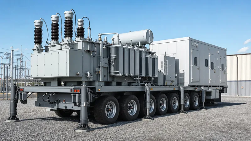
- A mobile substation is a fully factory-assembled, trailer-mounted or skid-mounted assembly housing high-voltage switchgear, a power transformer, medium-voltage switchgear, and auxiliary automation systems for rapid deployment.
- Road regulations typically constrain semi-trailer configurations to an axle load of 8 to 12 tonnes per axle and a gross vehicle weight under 40 to 60 tonnes without exceptional transport permits.
- Hybrid gas-insulated switchgear (GIS) or compact dead-tank circuit breakers are standard on mobile substations above 66 kV to satisfy severe dimensional clearances and transport shock constraints.
- Emergency deployment and temporary bypass operations demand pre-configured multifunction protective relays with plug-and-play multi-ratio current transformer inputs to match varying grid topologies.
- Factory testing to IEC 62271-202 and IEC 60076 must include dynamic deflection and vibration analysis to guarantee that transport stresses do not compromise core clamping or dielectric clearances.
Quick answer: A mobile substation is a completely self-contained, transportable electrical substation mounted on a multi-axle semi-trailer or structural skid, incorporating high-voltage switchgear, a power transformer, medium-voltage distribution switchgear, protection panels, and auxiliary AC/DC power systems to provide rapid, temporary grid connections during emergencies, planned overhauls, or remote site operations.
Electrical grid operators, EPC contractors, and industrial plants face severe operational disruption when primary substation assets fail unexpectedly or require major capital refurbishment. Constructing a permanent substation requires months or years of civil work, permitting, and equipment commissioning. A mobile substation compresses this deployment window from months to hours or days, delivering a complete transmission or distribution node that rolls directly onto the site fully wired, tested, and ready for primary cable or overhead line termination. Whether deployed as an emergency mobile substation following catastrophic transformer failure or as temporary infrastructure during busbar upgrades, these units maintain system reliability and avoid costly customer outages.
Modern mobile substation solutions represent a sophisticated intersection of heavy electrical plant engineering and vehicle transport dynamics. Equipment selection must balance high electrical ratings—often up to 145 kV or 245 kV primary transmission voltages and transformer capacities exceeding 63 MVA—against strict highway bridge loadings, turning radiuses, and vertical profile limitations. Understanding the core structural, electrical, and thermal constraints of these transportable platforms is critical for engineers preparing procurement specifications or evaluating supplier architectures.
What Is a Mobile Substation and How Does It Work?
A mobile substation functions as an autonomous, plug-and-play substation bay that replicates all electrical, mechanical, and protection functions of a permanent substation installation within a mobile envelope. Its operational purpose is to step down transmission or sub-transmission voltages to distribution levels, or to intermediate industrial voltages, while providing full system protection, metering, isolation, and remote supervisory control and data acquisition (SCADA) integration.
The assembly comprises four primary functional zones mounted systematically along a heavy-duty chassis:
- High-voltage (HV) incoming bay: Incorporates incoming termination points (such as surge arresters, disconnector switches, instrument transformers, and an SF6 or vacuum circuit breaker) engineered to clear upstream faults and provide safe system isolation.
- Mobile transformer substation core: An oil-immersed or specialized dry-type power transformer engineered with low-profile tank geometry, high mechanical shock resistance, and forced liquid cooling (ONAN/ONAF or ODAF) to maximise power density within physical weight limits, frequently detailed in our substation transformer engineering guide.
- Medium-voltage (MV) outgoing switchgear: Metal-enclosed or metal-clad switchgear bays housed inside an environmentally controlled, walk-in or aisle-less enclosure, providing outgoing circuit breakers, feeder protection, and auxiliary station power.
- Auxiliary and control infrastructure: An onboard station battery bank, battery charger, dual AC auxiliary sources, pre-wired protection and control panels, and fire detection systems that operate independently of external station supplies.
When energized, incoming transmission conductors attach directly to high-voltage bushings or flexible plug-in terminations on the HV deck. Power flows through the incoming circuit breaker into the primary winding of the transformer. The stepped-down secondary voltage routes via fully insulated, shielded busbar links or flexible MV cables into the onboard electrical switchgear. From there, multiple outgoing distribution feeders connect to the local grid or plant network via bottom-entry or side-mounted cable glands, restoring distribution service seamlessly.
Key Mobile Substation Solutions: Trailer vs Skid-Mounted Designs
Mobile substation configurations divide broadly into road-going trailer assemblies and heavy-duty structural skids, with selection dictated by relocation frequency, site terrain, and gross vehicle weight constraints. Both variations serve critical operational needs across distinct sectors.
A mobile substation trailer incorporates custom multi-axle running gear, hydraulic levelling outriggers, kingpin connections, and air braking systems complying with international highway freight regulations. These units are optimised for rapid transport across public road networks at highway speeds, requiring minimal site preparation beyond a compacted level pad. In contrast, a portable electric substation constructed on a structural steel skid is engineered for industrial dragging, flatbed hauling, or crane lifting. Skid-mounted designs dominate heavy civil operations, rail corridors, and resource extraction projects where rough terrain renders road trailers impractical.
| Engineering Parameter | Mobile Substation Trailer | Skid-Mounted Portable Substation | Containerised Portable Substation |
|---|---|---|---|
| Mobility Method | Semi-trailer with multi-axle steerable bogies | Structural skid base (oilfield/mine drag) | Standard ISO container chassis or flat rack |
| Maximum Voltage Rating | Up to 245 kV HV / 36 kV MV | Up to 66 kV HV / 13.8 kV MV | Up to 40.5 kV HV / 0.415–11 kV MV |
| Maximum Transformer Rating | Up to 63 MVA (ODAF cooling) | Up to 20 MVA (ONAF cooling) | Up to 6.3 MVA (compact dry or oil) |
| Site Civil Requirements | Compacted gravel pad; rated soil bearing | Crushed rock pad; steel rail sleds | Standard concrete pad or pier footings |
| Typical Relocation Setup Time | 4 to 12 hours (hydraulic legs) | 12 to 36 hours (crane/winch required) | 8 to 24 hours (side-loader crane) |
| Highway Transport Compliance | Direct road registration; axle-weight permits | Requires heavy-haul drop-deck transport | Standard ISO freight dimensions |
| Primary Operational Sector | Electric utilities, grid interconnects | Surface mining, drilling, tunneling | Commercial solar, wind, and data centres |
For high-capacity utility requirements exceeding 30 MVA at 110 kV or higher, split-trailer systems are frequently deployed. One semi-trailer accommodates the high-voltage breaker and disconnector deck, while a second trailer supports the power transformer, neutral earthing equipment, and medium-voltage switchgear. They are linked on-site using pre-assembled flexible busbars and rapid multi-pin control umbilical cables, effectively bypassing single-chassis highway axle weight limits.
Primary Applications: From Utility Grid Resilience to Portable Substations for Mining
Mobile substations are deployed across diverse operating environments where capital construction is uneconomic, power access must precede civil development, or unscheduled downtime carries catastrophic financial costs. The four primary commercial applications each impose unique engineering demands on equipment design.
1. Utility Grid Emergency and Capital Asset Maintenance: Electric utilities maintain an emergency mobile substation fleet to guarantee network resilience against transformer failures, severe weather events, or switchyard fires. Furthermore, during scheduled maintenance on aging permanent substations, a mobile unit bridges the load demand, allowing engineers to de-energise busbars, recondition breakers, and execute upgrades without implementing rolling blackouts.
2. Portable Substations for Mining: Open-pit extraction, underground tunneling, and quarry operations expand geographically as working faces advance. Portable substations for mining deliver ruggedised power directly to mobile draglines, electric shovels, haul-truck charging stations, and dewatering pumps. These units feature reinforced skid frames, dynamic vibration dampeners, ingress protection up to IP65, and specialised neutral grounding resistor (NGR) systems coupled with sensitive earth-leakage monitoring to protect personnel working in damp, high-fault-current environments.
3. Industrial Mobile Substation Solutions for Oil and Gas: Temporary drilling rigs, pipeline pumping stations, and refinery turnaround operations rely on specialised industrial mobile substation solutions for oil and gas. In these installations, electrical equipment must comply with hazardous area zoning requirements (ATEX / IECEx or NEC Class I, Division 2). Engineering specifications mandate positive-pressure purge systems inside control cabins, sealed cable transits, flameproof enclosures, and high-specification synthetic ester or silicone dielectric fluids to eliminate fire hazards in hydrocarbon-rich atmospheres.
4. Mobile Substation Rental for Capital Projects and Renewables: The expanding market for mobile substation rental supports large-scale infrastructure projects, such as offshore wind onshore substations, utility-scale solar grid injection, and major transport electrification schemes. Project developers rent mobile substations to energise downstream equipment and commence pre-commissioning months before local transmission utilities complete permanent grid interconnection assets.
Engineering Architecture: High-Voltage Switchgear and Transformer Integration
Integrating full-scale substation equipment onto a restricted road chassis requires rigorous mechanical, dielectric, and thermal optimisation. Every millimetre of clearance and kilogram of weight must be accounted for according to international design standards.
On the high-voltage side, traditional open-air busbar layouts are impractical due to phase-to-phase and phase-to-earth electrical clearance requirements (such as minimum strike distances stipulated in IEC 61936-1). Consequently, engineers deploy compact gas-insulated switchgear (GIS) or hybrid switchgear modules (pass-through modules combining circuit breakers, disconnectors, earthing switches, and current transformers in an SF6-sealed or alternative gas enclosure). When open-air terminations are utilised below 72.5 kV, scissor-type or vertical pantograph disconnectors with folding mechanism frames are specified to maintain highway clearance profiles during transit and extend to standard dielectric heights once parked on-site.
The central transformer must achieve maximum capacity within minimum dimensions. Mobile units typically incorporate a high-temperature insulation class (such as aramid paper or hybrid thermal class 155°C/180°C systems per IEC 60076-14) paired with synthetic or natural ester dielectric fluids. This enables the transformer to run at elevated winding temperature rises (up to 95°C or 115°C rise) without degrading paper insulation life, allowing the core and coil assembly to be scaled down significantly compared to standard substation transformers. Cooling systems feature directed forced-oil forced-air (ODAF) radiators mounted flush along the trailer sidewalls, equipped with variable-speed low-noise fans.
Protection architecture requires comprehensive redundancy. Engineers specify multifunctional digital numerical protection relays incorporating differential protection (87T), overcurrent and earth fault protection (50/51/51N), overexcitation protection (24), and sudden pressure relays (63). Integrating pre-configured settings groups into the numerical relays allows the mobile unit to adapt instantaneously to varying host substation settings without field reprogramming, a topic addressed in detail in our transformer protection engineering guide.
Specification Checklist and Sizing Criteria for Mobile Power Substation RFQs
Procuring a custom mobile substation requires precise technical definition across electrical, transport, and site interface parameters to avoid expensive factory change orders or transport rejection. EPC contractors and procurement managers can utilize the following engineering checklist when formulating a Request for Quotation (RFQ).
| Specification Domain | Key Design Parameter | Standard Sizing / Selection Criteria | Standard Reference |
|---|---|---|---|
| Primary Electrical Ratings | Rated Voltage & Insulation Level | Nominal system kV, Maximum operating kV, BIL (e.g., 110 kV, 550 kV BIL) | IEC 60071-1 / IEEE C57.12.00 Table 5 |
| Transformer Sizing | Rated MVA & Vector Group | ONAN/ONAF/ODAF ratings; Multi-voltage windings; Dyn11 / YNd11 selectability | IEC 60076-1 clause 5.4 |
| Impedance Limits | Percent Impedance (%Z) | Optimised for short-circuit limit vs voltage drop (typically 8.0% to 12.5%) | IEC 60076-5 |
| HV Switchgear Type | Breaker & Disconnector Platform | Hybrid GIS / Dead-tank vacuum / SF6 module with motor-operated isolators | IEC 62271-200 / IEEE C37.20.2 |
| MV Switchgear Array | Feeder Count & Arc Classification | Metal-clad vacuum switchgear; IAC AFLR rating up to 31.5 kA / 1s | IEC 62271-200 clause 6.106 |
| Axle & Weight Limits | Maximum Gross Vehicle Weight (GVW) | Calculated per axle (typically 9,000 kg to 12,000 kg max per axle line) | Local Transport Authority Limits |
| Chassis Mechanics | Suspension & Levelling Mechanism | Air-ride / hydraulic suspension; integrated hydraulic levelling outriggers | ISO 1496 / Heavy Haul Freight Codes |
| Auxiliary Power | Station Battery & Dual AC Inputs | 110V or 220V DC VRLA/NiCd (10-hr autonomy) + 400V/230V auto-transfer switch | IEEE 484 / IEC 60896 |
| Environmental Range | Operating Ambient & Ingress | -40°C to +50°C; weatherproof control rooms; marine-grade paint finish | ISO 12944 / IEC 60529 |
When selecting transformer capacity, calculate prospective system load curves using established engineering methodologies or an automated kVA calculator to size forced-cooling thresholds accurately. Specifying dual or triple secondary voltages (such as 11 kV, 22 kV, and 33 kV selectable via a de-energised tap changer or external terminal board) increases fleet asset utilisation across varied geographic distribution zones.
Transport Logistics, Road Clearances, and Site Commissioning Procedures
Transporting an oversized mobile power substation across public infrastructure and placing it into operation involves strict logistics coordination and sequential on-site commissioning.
During route planning, engineers must verify bridge ratings, overhead line heights, turning radii, and road inclinations. Heavy multi-axle trailers frequently incorporate hydraulic goose-necks and independently steerable rear bogies operated by remote control to navigate tight urban corners and mountainous mine access switchbacks. Once delivered to the operating pad, the unit must undergo a structured commissioning sequence to ensure personnel safety and plant integrity.
- Positioning and Levelling: Position the trailer or skid on the designated, compacted pad. Deploy the integrated hydraulic outriggers to raise the chassis off the mechanical suspension, levelling the frame precisely using built-in spirit or electronic tilt sensors. Lock mechanical safety collars on each outrigger cylinder.
- Substation Grounding Interconnection: Bond the onboard copper grounding busbar (minimum 50x5 mm copper cross-section) to the local substation earth grid or driven earth rods at multiple points, confirming grounding resistance meets standard criteria (typically < 1.0 Ohm per IEEE 80).
- Mechanical Deployment: Erect folding HV gantry structures, swing out lightning masts, mount surge arresters if unbolted for transit, and install anti-vibration transit locks into their neutral operational positions.
- Auxiliary Supply Energisation: Connect an external 400V utility feed or start the onboard auxiliary diesel/solar generator to energise battery chargers, internal enclosure climate controls, and relay protection panels.
- Dielectric and Insulation Integrity Testing: Execute insulation resistance checks, transformer winding resistance, and oil dielectric breakdown voltage tests (minimum 50 kV per IEC 60156) to confirm no moisture or gas ingress occurred during rough transport.
- Secondary Injection and Tripping Logic: Perform secondary current and voltage injection on all protection loops, validating that circuit breaker trip coils, emergency stops, lockout relays, and SCADA alarms fire accurately.
- HV and MV Cable Terminations: Secure primary transmission spans to the HV terminal pads and plug fully screened separable connectors or terminate flexible cables into the MV switchgear feeder compartments.
- Final Phasing and Energisation: Verify phase rotation against the host system, close the HV incoming breaker under open-circuit secondary conditions, observe transformer magnetising inrush damping, verify MV busbar voltages, and sequentially close outgoing distribution feeders.
Evaluating Mobile Substation Manufacturers and Sourcing Considerations
Selecting qualified mobile substation manufacturers requires thorough scrutiny beyond standard static transformer capability. A mobile asset represents a hybrid electro-mechanical platform where structural failure of the chassis during high-speed highway transit can catastrophic destroy millions of dollars of precision electrical plant.
First, verify that prospective portable power substation manufacturers possess complete in-house fabrication, finite element analysis (FEA), and torsional stress-testing facilities. The trailer chassis must absorb dynamic twisting moments, braking g-forces, and lateral wind loads without transferring structural deflection into the core clamping structure or porcelain/composite transformer bushings. Inquire whether the manufacturer tests completed units according to dynamic transport vibration guidelines (such as IEC 60068-2-6 or military standard MIL-STD-810G).
Second, examine the factory acceptance testing (FAT) protocol. A fully qualified manufacturer must assemble the complete substation—including high-voltage switchgear, transformer, medium-voltage switchgear, and auxiliary cabling—on its trailer chassis and conduct comprehensive integrated system testing at the factory floor before dispatch. Routine tests per IEC 62271-202 (High-voltage/Low-voltage prefabricated substations) and complete operational interlocking tests must be witnessed and certified, ensuring zero structural or wiring modifications are required in the field.
Third, assess the manufacturer's integration of global component standards. Because these substations operate across fluctuating grid conditions, internal control systems, relays, switchgear parts, and instrument transformers should originate from internationally recognized suppliers with easily accessible local spare parts pipelines. This guarantees decades of reliable operation and simplifies asset management across utility fleets.
Next steps: specifying and sourcing
When specifying a mobile substation, prepare a complete single-line diagram, site dimensional constraints, required HV/MV voltage combinations, prospective fault currents, and transport axle-load limits. Our engineering team designs and manufactures fully integrated mobile substation solutions, custom skid assemblies, and containerised switchgear tailored to utility, mining, and industrial environments worldwide. Explore our factory capabilities across prefabricated transformer substations, high-performance power transformers, and high-reliability HV and LV switchgear systems. To discuss your project parameters, request a comprehensive technical proposal, or receive budget pricing, submit your project data directly through our request a quote page or contact our application engineering team via the contact page.
Frequently asked questions
What is the typical deployment time for a mobile substation?
A mobile substation can typically be deployed and fully energized within 4 to 24 hours of arriving on site. Setup duration depends on whether the unit uses pre-erected hybrid gas-insulated switchgear or folding overhead disconnectors, plus the time required to complete earthing grid bonding and cable terminations.
What is the maximum capacity possible on a mobile substation trailer?
Maximum capacity typically reaches 63 MVA at system voltages up to 245 kV on a single specialised multi-axle trailer utilizing forced ester-oil cooling (ODAF). Capacities up to 100 MVA can be achieved by splitting the high-voltage switchgear and the power transformer across two interconnected trailers to meet highway axle limits.
How do mobile substations comply with road weight and height limits?
Manufacturers utilize high-tensile steel chassis, lightweight aramid or high-temperature insulated transformer windings, synthetic ester fluids, and compact gas-insulated switchgear to minimize mass. Equipment is engineered within standard low-bed trailer profiles (typically under 4.3 metres transit height) and uses multi-axle hydraulic suspension lines to keep axle weights below 10 to 12 tonnes.
Can a mobile substation operate permanently?
Yes, mobile substations can operate continuously for months or years if properly serviced, grounded, and maintained according to standard substation maintenance protocols. However, they are engineered with higher capital-cost compact components; prolonged permanent installation may tie up valuable emergency response assets that are better reserved for rapid grid recovery.
What is the difference between a mobile substation and a compact prefabricated substation?
A mobile substation is built onto a wheeled trailer or heavy structural transport skid with integrated levelling outriggers and quick-connect terminations designed for frequent road relocation. A compact prefabricated substation is delivered in a fixed concrete or metal housing meant to be craned onto a permanent foundation for permanent distribution service.
Tags: mobile substation mobile substation solutions portable substation mobile power substation emergency mobile substation


