Key takeaways
- A substation transforms voltage, switches circuits and clears faults; it does not generate electricity, but connects generation, transmission and distribution networks together.
- Transmission substations commonly operate from about 69 kV up to 765 kV, while distribution substations step down to medium voltages such as 11, 13.8 or 33 kV.
- Core substation components include power transformers, circuit breakers, disconnect switches, instrument transformers, surge arresters, busbars, protection relays and a grounding grid.
- Current falls as voltage rises: a 20 MVA transformer draws about 105 A at 110 kV but roughly 1,050 A at 11 kV, from I = S / (√3 × V).
- Small substations such as pad-mounted transformers and compact box-type units supply individual buildings or sites, typically at 11–35 kV primary and 400 V or 480 V secondary.
Quick answer: A substation is a node in the power system where voltage is transformed, circuits are switched and faults are isolated. It uses transformers to step voltage up or down, circuit breakers and disconnectors to connect and separate lines, and protection relays to detect faults. Substations link generation, high-voltage transmission and the distribution networks that feed homes, buildings and industry.
Every kilowatt-hour delivered to a factory or a home passes through several substations on its way from the generator. Yet the fenced yard of insulators and transformers at the edge of town is one of the least understood parts of the grid. People search for a substation meaning when a new one is proposed nearby, when they start a career in power engineering, or when a project needs its own supply point.
This explainer is for students, facility managers, developers and junior engineers. It defines an electrical substation, explains what it does and how it works, compares the main types, and lists the substation equipment you will find inside, from 400 kV transmission yards to small 11 kV distribution units.
What Is an Electrical Substation? Definition and Meaning
An electrical substation is an assembly of transformers, switching devices, protection and control equipment, installed at a point where power lines meet, to change voltage, direct power flow and protect the network. That is the working power substation definition used by utilities and in standards such as IEC 61936-1, which covers power installations above 1 kV AC.
The prefix “sub” comes from early electrification, when the power station was the main station and smaller stations fed from it were substations. The term stuck, and today it applies to everything from a 765 kV switching yard to a small sub station feeding a housing estate.
Three things distinguish a substation from other electrical equipment:
- It connects circuits at different voltages or from different directions, through transformers or a common busbar.
- It contains switching devices that can interrupt load and fault currents.
- It contains protection that detects faults and trips the right breaker within fractions of a second.
A substation does not generate electricity. A power plant has its own step-up substation, but the generation itself is separate. When people ask for an electric substation meaning in plain terms: it is the grid's junction box, transformer station and circuit breaker panel combined, operating at voltages from a few kilovolts up to several hundred kilovolts. For the voltage bands involved, see our guide to LV, MV, HV and EHV voltage classes.
What Does a Substation Do?
What electrical substations do can be grouped into five functions. Most substations perform several of them at once.
- Transform voltage. Step-up substations at power plants raise generator voltage (typically 11–25 kV) to transmission levels such as 220 kV or 400 kV. Step-down substations reduce it again for sub-transmission and distribution.
- Switch and reconfigure circuits. Breakers and disconnectors connect and disconnect lines and transformers for maintenance, load transfer or network reconfiguration.
- Protect the network. Relays measure current and voltage through instrument transformers and trip breakers when a short circuit or earth fault occurs, limiting damage and keeping the rest of the grid stable.
- Regulate voltage and power flow. On-load tap changers, capacitor banks, reactors and sometimes phase-shifting transformers keep voltage within limits and steer power flow.
- Measure and communicate. Metering, SCADA and automation systems report the state of the network to control centers.
Why transmit at high voltage?
For the same power, a higher voltage means a lower current, and line losses scale with the square of current. Using I = S / (√3 × V) for a 20 MVA three-phase load:
- At 110 kV:
I = 20,000,000 / (1.732 × 110,000) ≈ 105 A - At 11 kV:
I = 20,000,000 / (1.732 × 11,000) ≈ 1,050 A
Ten times the voltage gives one tenth the current and roughly one hundredth of the I²R loss in the same conductor. That is the reason substations exist at each change of voltage level. The electric power distribution engineering guide follows the whole chain from generation to the meter.
How Does a Power Substation Work?
How a power substation works is easiest to follow along the path of power through a typical step-down distribution substation.
- Incoming line: an overhead line or cable arrives at a line entrance structure, passes a surge arrester that diverts lightning and switching surges to ground, and a line disconnector that provides a visible isolation point.
- Measurement: current transformers and voltage transformers scale primary values down to 1 A or 5 A and 100–120 V for relays and meters.
- Circuit breaker: the HV breaker can interrupt fault currents of tens of kiloamperes within a few cycles when a relay commands a trip.
- Power transformer: steps voltage down, for example 110 kV to 11 kV, with an on-load tap changer holding the secondary voltage constant as load varies.
- MV switchgear: the transformer feeds an MV busbar through an incomer breaker; outgoing feeder breakers supply distribution lines or cables.
- Protection and control: relays in the control building compare measurements against settings and trip the nearest breaker on a fault, while SCADA reports status to the control center.
- Grounding: a buried copper grid under the whole site bonds every structure, keeping step and touch voltages safe during faults.
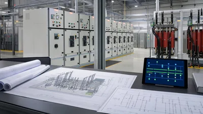
A one-line diagram shows this chain with standard symbols. Our electric substation diagram guide walks through typical layouts, and the substation protection engineering guide explains how relays coordinate so only the faulted section is disconnected.
Types of Electrical Substation
Substations are classified by function in the network, by voltage, and by insulation technology. The functional classification is the most useful.
| Type | Function | Typical voltages |
|---|---|---|
| Generator step-up substation | Raises plant output to transmission voltage | 11–25 kV to 110–500 kV |
| Transmission substation | Interconnects transmission lines, transforms between transmission levels | 69–765 kV |
| Switching substation | Switches lines at one voltage, no transformation | Any transmission voltage |
| Sub-transmission / zone substation | Steps down to sub-transmission or primary distribution | 66–220 kV to 11–33 kV |
| Distribution substation | Feeds local MV network | 33–69 kV to 4–35 kV |
| Secondary / consumer substation | Steps MV to LV for buildings | 11–35 kV to 400 V or 480 V |
| Collector substation | Gathers output of wind or solar plants | 33–35 kV to 110–230 kV |
| Converter substation | Converts AC to DC for HVDC links | HVDC ±100 kV and above |
| Industrial substation | Supplies a plant from the utility | MV or HV to plant MV/LV |
By insulation, an air-insulated substation (AIS) uses open-air clearances, while a gas-insulated substation (GIS) encloses live parts in SF6 or alternative gas, cutting land area dramatically. See the gas-insulated switchgear guide for the trade-offs. Newer designs replace copper control wiring with fiber-optic process buses, described in our digital substation guide.
Electrical Substation Equipment and Components
Electrical substation equipment varies with voltage and function, but the same core substation parts appear in almost every installation.
| Component | Purpose | Governing standards |
|---|---|---|
| Power transformer | Changes voltage level; may include on-load tap changer | IEC 60076, IEEE C57.12.00 |
| Circuit breaker | Interrupts load and fault current | IEC 62271-100, IEEE C37.04/C37.06 |
| Disconnector (isolator) | Provides visible isolation; not for load breaking | IEC 62271-102 |
| Earthing switch | Grounds de-energized equipment for safe work | IEC 62271-102 |
| Current and voltage transformers | Scale current and voltage for protection and metering | IEC 61869, IEEE C57.13 |
| Surge arrester | Limits overvoltages from lightning and switching | IEC 60099-4, IEEE C62.11 |
| Busbars and insulators | Collect and distribute power between bays | IEC 60865 for short-circuit forces |
| MV switchgear | Enclosed breakers or RMUs for outgoing feeders | IEC 62271-200, IEEE C37.20.2 |
| Protection relays and SCADA | Fault detection, control and monitoring | IEC 61850, IEC 60255 |
| Station battery and chargers | Keep protection and tripping alive during outages | IEEE 485 for sizing |
| Grounding grid | Controls step and touch voltages | IEEE 80 |
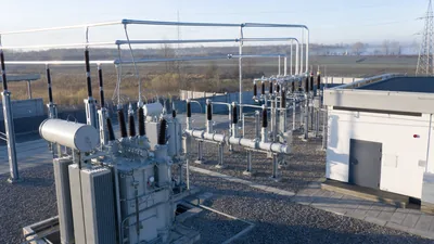
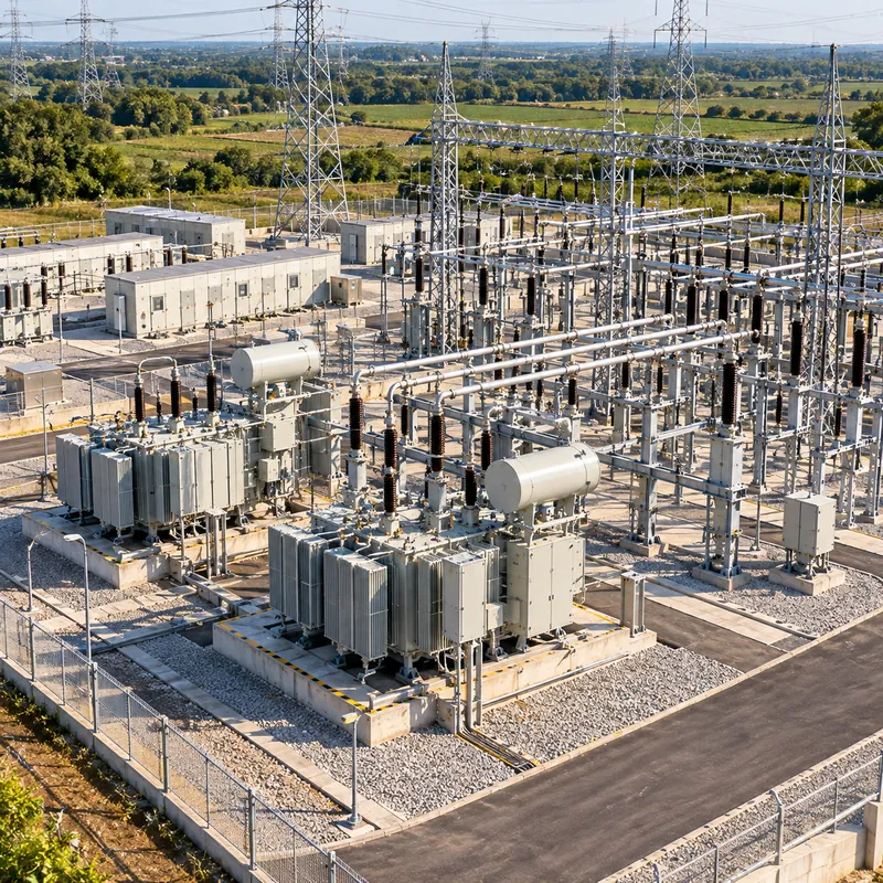
Auxiliary systems complete the picture: station service transformers for lighting and heating, fire protection, oil containment, fencing and security. A substation substation search often comes from people trying to identify these items in a photo; the transformers are the large tanks with radiators, breakers sit in bays beside them, and the tall slim columns are usually CTs, VTs or arresters.
Small Substations: Distribution Units for Buildings and Sites
Not every substation is a fenced yard. A small electricity substation may be a single pad-mounted transformer on a residential street, a kiosk-type compact substation at a factory gate, or a room inside a building basement. These are the points where utility power becomes usable low voltage.
- Pad-mounted transformer: a tamper-resistant cabinet with MV terminations on one side and LV on the other, common in North American underground distribution at 15–35 kV primary.
- Pole-mounted transformer: an overhead distribution transformer, usually single-phase in the US, with a fuse cutout and arrester; technically a very small substation.
- Compact (box-type) substation: an enclosure with MV switchgear or a ring main unit, a distribution transformer up to about 2,500 kVA and an LV board, factory assembled and tested.
- Unit substation: indoor transformer close-coupled to MV and LV switchgear, used in industrial plants and data centers.
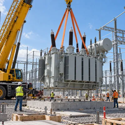
For a site owner, choosing between these depends on load, utility requirements, available space and whether the site needs MV switching. Our unit substation engineering guide covers indoor arrangements, and the substation construction guide explains what is involved in building a larger yard. Substation work around any of these units must be done by qualified, authorized personnel, because high-voltage parts can remain energized even when the low-voltage side is off.
Next Steps: Specifying and Sourcing a Substation
If your project needs its own supply point, start the substation specification with these inputs:
- Utility supply voltage, available fault level and grounding system at the point of connection.
- Maximum demand in kVA, expected growth and load profile, which set transformer rating and number of units.
- Required LV or MV output voltage, frequency (50 or 60 Hz) and the distribution architecture downstream.
- Redundancy: single transformer, N+1, or ring main configuration.
- Site constraints: footprint, indoor or outdoor, altitude, ambient temperature and enclosure rating.
- Standards: IEC 60076 and IEC 62271, or ANSI/IEEE variants for North American utilities.
MARS manufactures compact box-type and containerised substations, pad-mounted and pole-mounted transformers, power transformers to 31,500 kVA in the 110 kV class, and MV/LV switchgear, all routine tested before shipment. Browse the transformer substation range or check transformer capacity with the transformer sizing calculator, then send your requirements through the quote request page.
Frequently asked questions
What is the purpose of a substation?
The purpose of a substation is to change voltage between network levels, switch circuits for operation and maintenance, and protect the grid by isolating faults. It also regulates voltage and provides measurements to control centers. Without substations, power could not move efficiently from high-voltage transmission lines to the medium and low voltages used by customers.
What is the difference between a transmission substation and a distribution substation?
A transmission substation operates at high or extra-high voltage, typically 69 kV to 765 kV, and interconnects transmission lines or steps between transmission levels. A distribution substation takes power from sub-transmission and steps it down to medium voltage, such as 11, 13.8 or 33 kV, for feeders that supply neighborhoods and commercial or industrial customers.
Is it safe to live near an electrical substation?
Substations are designed with fences, clearances and grounding grids so that the public outside the fence is not exposed to electrical hazards. Magnetic fields fall off rapidly with distance and are typically close to background levels at the fence line or a short distance beyond. The main safety rule is never to enter a substation or touch its fence equipment.
What equipment is found in a substation?
Typical substation equipment includes power transformers, circuit breakers, disconnect switches, earthing switches, current and voltage transformers, surge arresters, busbars and insulators, MV switchgear, protection relays, SCADA, station batteries and chargers, and a buried grounding grid. Larger sites also have capacitor banks, reactors and control buildings.
How does a substation reduce voltage?
A substation reduces voltage with a power transformer. The primary winding is connected to the high-voltage line and the secondary winding has fewer turns, so the output voltage is lower in proportion to the turns ratio. An on-load tap changer adjusts the ratio in small steps to keep the output voltage within limits as load changes.
What is a small substation called?
Small substations are usually called secondary substations, distribution substations, compact or box-type substations, kiosk substations or pad-mounted transformers, depending on region. They step medium voltage, such as 11 kV or 13.8 kV, down to 400 V or 480 V for individual buildings, campuses or industrial sites.
Written and reviewed by the MARS application engineering team in Shanghai, who specify and test transformers, switchgear, substations and battery storage for projects in 40+ countries. Last updated .
Tags: what is a substation electrical substation equipment substation components distribution substation transmission substation