Key takeaways
- Medium voltage power systems operate between 1 kV and 35 kV according to IEC 60038 and IEEE 1585 standards.
- Stepping voltage up to medium voltage cuts line current proportionally, reducing conductor I²R thermal losses by a factor of four when doubling line potential.
- Radial topologies offer the lowest capital cost, while closed-loop and primary selective architectures provide higher reliability through automated bus transfer schemes.
- Vacuum circuit breakers dominating 12 kV to 36 kV installations typically achieve short-circuit breaking ratings from 25 kA to 40 kA within three to five cycles under IEC 62271-100.
- Medium voltage mechanical systems require strict structural anchoring to resist electromechanical dynamic forces exceeding tens of kilonewtons during short-circuit peak currents.
Quick answer: Medium voltage power refers to electrical distribution networks operating between 1 kV and 35 kV AC, acting as the critical link between bulk high-voltage transmission grids and low-voltage end-user equipment. It delivers bulk electrical energy efficiently over industrial campuses, commercial infrastructure, and utility feeders while keeping conductor sizes, line losses, and equipment footprints within practical physical limits.
In modern industrial facilities, data centres, and renewable generation plants, deploying an optimised medium voltage power network is essential for handling megawatt-scale loads. Stepping distribution up above standard low-voltage thresholds (such as 400 V or 480 V) reduces line current proportionally, mitigating catastrophic voltage drop over long feeder runs and dramatically reducing copper expenditures. Understanding the parameters of medium voltage engineering enables project teams to balance reliability, capital expenditure, and operational safety across the lifetime of the electrical installation.
Voltage Classifications in Medium Voltage Electrical Systems
Medium voltage electrical systems are formally classified by international standards organizations to establish clear insulation coordination, clearance boundaries, and testing protocols. According to IEC 60038 (IEC Standard Voltages), medium voltage encompasses operating nominal values above 1 kV AC up to 35 kV AC, whereas IEEE 1585 and ANSI C84.1 define medium voltage as spanning 1 kV up to 72.5 kV. In practical industrial engineering, the 1 kV to 36 kV band captures the overwhelming majority of plant distribution networks.
Specifying equipment within these bands requires rigorous alignment between nominal operating voltage, maximum design voltage (Ur), and basic impulse insulation level (BIL). Under IEC 60071-1 clause 5, insulation levels must withstand both continuous operating stresses and transient overvoltages triggered by lightning strikes or vacuum switching operations. The table below outlines the standardised voltage classes commonly deployed across global industrial distribution infrastructure.
| Nominal System Voltage (kV RMS) | Maximum Equipment Voltage Ur (kV RMS) | Rated Power Frequency Withstand (kV RMS, 1 min) | Rated Impulse Withstand BIL (kV Peak, 1.2/50 µs) | Standard Reference |
|---|---|---|---|---|
| 3.3 / 4.16 | 7.2 | 20 | 60 | IEC 60071-1 / IEEE C37.20.2 |
| 6.6 / 7.2 | 7.2 / 8.7 | 20 | 60 / 75 | IEC 60071-1 / ANSI C84.1 |
| 11.0 / 13.8 | 12.0 / 15.0 | 28 / 36 | 75 / 95 | IEC 62271-1 / IEEE C37.20.2 |
| 22.0 / 24.0 | 24.0 | 50 | 125 | IEC 62271-1 Table 1 |
| 33.0 / 34.5 | 36.0 / 38.0 | 70 | 170 / 200 | IEC 60071-1 / IEEE C37.20.2 |
Medium Voltage Power Distribution Topologies and Architecture
Medium voltage power distribution architecture dictates how electrical energy flows from primary utility substations to downstream load centres. Choosing the correct feeder configuration determines plant availability, fault tolerance, maintenance flexibility, and upfront capital expenditure. Industrial facilities generally deploy one of three core topologies: radial distribution, primary selective, or looped ring systems.
A radial architecture employs a single path between the power source and the load bus. While radial layouts minimise capital cost and protective relay complexity, an equipment failure on the incoming cable or busbar causes a complete blackout downstream. For facilities requiring higher continuity of service, a primary selective scheme uses two independent medium voltage feeders feeding a common switchgear line-up equipped with an automatic transfer switch (ATS) or bus-tie circuit breaker. As detailed in our radial feed vs loop feed distribution guide, ring main architectures provide redundant power paths, permitting isolating switches to de-energise faulted cable sections without interrupting adjacent secondary substations.
Core Equipment in Medium Voltage Electrical Installations
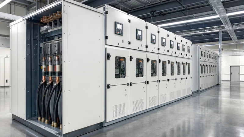
Primary medium voltage electrical installations consist of switchgear assemblies, power transformers, protective instrument transformers, and surge protection devices. The primary control and switching functions occur inside metal-enclosed or metal-clad switchgear built to IEC 62271-200 or IEEE C37.20.2. Modern installations rely on vacuum circuit breakers (VCB) or sulphur hexafluoride (SF6) gas-insulated modules to interrupt load and fault currents reliably.
For facilities prioritising robust compartmentalisation and personnel safety, specifying metal-clad switchboard construction ensures grounded metal barriers separate the circuit breaker, main busbars, incoming cable terminations, and low-voltage control compartments. To explore the internal compartment criteria and breaker racking mechanisms, review our comprehensive MV switchgear engineering guide. Current transformers (CT) and voltage transformers (VT) step down primary operating variables to feed numerical protection relays, which execute overcurrent (ANSI 50/51), earth fault (ANSI 50N/51N), and differential (ANSI 87) protection algorithms.
Medium Voltage Mechanical Systems and Structural Dynamics
Medium voltage mechanical systems govern the structural enclosures, busbar bracing, thermal ventilation passages, and physical interlocks that maintain switchgear integrity during operational and fault events. During a phase-to-phase or three-phase short-circuit fault, electromagnetic forces between parallel conductors are proportional to the square of the peak fault current (Ip²), as defined by IEC 60865-1. These electromechanical forces routinely exert stresses exceeding 20 kN per linear metre on busbar supports.
Switchgear enclosures must withstand these dynamic mechanical loads without permanent structural deformation or insulator cracking. Mechanical interlocks prevent hazardous operational sequences, such as attempting to rack out a closed circuit breaker, closing an earth switch onto an energised cable, or opening cable compartment panels before closing the integral earthing switch. Furthermore, arc-resistant construction tested according to IEC 62271-200 Annex AA incorporates mechanical pressure-relief flaps that vent superheated gases upwards into dedicated exhaust plenums, protecting personnel standing in front of or beside the assembly.
Worked Engineering Calculation: Sizing Medium Voltage Feeders and Breakers
Accurate medium voltage engineering demands precise calculation of continuous full-load currents, short-circuit levels, and cable thermal withstand ratings. Consider an industrial facility adding an 8,000 kVA load block powered by an 11 kV, 3-phase, 50 Hz feeder backed by a utility source delivering a prospective 25 kA symmetrical short-circuit current with a fault clearing time of 0.5 seconds.
First, calculate the rated full-load current (Ifl) of the load block:
Ifl = S / (√3 × V) = 8,000 kVA / (1.732 × 11 kV) = 419.9 A
A circuit breaker with a nominal continuous current rating of 630 A or 1,250 A is selected to provide adequate operating margin and thermal headroom. Next, determine the prospective short-circuit apparent power (Sk) to size the breaking capacity:
Sk = √3 × V × Isc = 1.732 × 11 kV × 25 kA = 476.3 MVA
Under IEC 62271-100, the circuit breaker must feature a rated short-circuit breaking current of at least 25 kA RMS and a peak withstand capability (Ip) calculated with an asymmetry factor (typically 2.5 for 50 Hz systems):
Ip = 2.5 × 25 kA = 62.5 kA peak
Finally, calculate the minimum cross-sectional area (S_cable) of a copper conductor insulated with cross-linked polyethylene (XLPE) to survive the short-circuit thermal stress without exceeding its insulation limit (250 °C from a continuous 90 °C base), using the adiabatic equation from IEC 60364-5-54:
S_cable = (Isc × √t) / k
For copper conductors with XLPE insulation, the material constant k is 143 A·s½/mm². Substituting the parameters:
S_cable = (25,000 A × √0.5 s) / 143 = (25,000 × 0.7071) / 143 = 17,677.67 / 143 = 123.6 mm²
Consequently, the standard minimum cross-section required for fault withstand is 150 mm² per phase, even though continuous full-load current (420 A) would thermally allow a smaller conductor in free air. For more details on integrating breaker protection envelopes, see our medium voltage breaker selection guide.
Commissioning and Testing Procedures for MV Infrastructure
Commissioning medium voltage installations requires systematic pre-energisation testing to verify insulation integrity, protection coordination, and mechanical functionality under factory acceptance testing (FAT) and site acceptance testing (SAT) protocols. Following international standards such as IEEE 400 and IEC 62271-1, field engineers must execute a strict sequence of diagnostics prior to introducing system voltage.
- Insulation Resistance (IR) Testing: Apply a calibrated 2.5 kV or 5.0 kV DC test voltage between phases and from each phase to earth using a megohmmeter to ensure bulk resistance exceeds 1,000 MΩ.
- Contact Resistance Measurement: Perform micro-ohmmeter testing across circuit breaker vacuum bottle contacts and busbar bolting joints; readings should not exceed factory baseline figures (typically under 50 µΩ).
- Very Low Frequency (VLF) Withstand Testing: Subject medium voltage power cables to VLF AC withstand testing at 0.1 Hz per IEEE 400.2 to detect cable joint and insulation defects without degrading the cable dielectric.
- Current and Voltage Transformer Secondary Injection: Inject secondary current and voltage signals into the protection scheme to prove ratio accuracy, phase polarity, and tripping functionality of relays operating the shunt trip coils.
- Circuit Breaker Timing and Synchronisation: Measure opening, closing, and trip-free operational times using a breaker timing analyser to confirm pole discrepancies remain under 2 milliseconds according to manufacturer design limits.
To cross-reference complete pre-commissioning procedures for primary equipment, refer to our detailed substation testing and field commissioning guide.
Next Steps: Specifying and Sourcing Medium Voltage Systems
When preparing an inquiry or tender package for medium voltage distribution projects, engineering teams must supply key operational parameters to ensure accurate factory configuration. Essential data includes nominal and maximum system voltages, basic impulse level (BIL), prospective symmetrical and asymmetrical fault currents, ambient temperature extremes, elevation above sea level, single-line diagrams (SLD), and preferred communication protocols (such as IEC 61850 or Modbus TCP). Specifying arc flash containment ratings (IAC AFLR) ensures personnel safety during internal fault conditions. Explore our factory capabilities across engineered HV and LV switchgear and integrated prefabricated transformer substations, or submit your single-line diagrams directly through our engineering quote page to receive a tailored technical proposal.
Frequently asked questions
What is considered medium voltage power?
Medium voltage power encompasses electrical systems operating between 1,000 V (1 kV) and 35,000 V (35 kV) AC under IEC standards, or up to 72.5 kV under ANSI and IEEE standards. It is standardly deployed for regional distribution networks, commercial facilities, and industrial power plants.
Why is medium voltage used instead of low voltage?
Medium voltage is used instead of low voltage because higher voltages significantly lower the operating current for an equivalent power rating. This current reduction minimises I²R conductor heat losses, prevents unacceptable voltage drop over long distribution distances, and drastically reduces the cross-sectional copper size required for feeder cabling.
What circuit breakers are used in medium voltage switchgear?
Vacuum circuit breakers (VCB) and sulphur hexafluoride (SF6) circuit breakers are the standard interruption devices in medium voltage switchgear. Vacuum technology dominates 12 kV to 36 kV indoor applications due to its maintenance-free contacts, high electrical endurance, and zero greenhouse gas emissions.
What is the standard BIL for 11 kV and 33 kV systems?
Under IEC 60071-1, an 11 kV nominal system typically has a rated basic impulse insulation level (BIL) of 75 kV or 95 kV peak. A 33 kV system standardly carries a rated BIL of 170 kV peak against transient atmospheric lightning and switching surges.
How often does medium voltage switchgear require maintenance?
Routine visual inspections and partial discharge monitoring should occur every six to twelve months, while comprehensive mechanical lubrication, contact resistance testing, and protection trip timing are typically scheduled every three to five years depending on the operating environment and switching duty cycles.
Tags: medium voltage power medium voltage electrical medium voltage electrical systems medium voltage power distribution medium voltage engineering


