Key takeaways
- Medium voltage electrical systems operate between 1 kV and 35 kV under IEC standards and up to 69 kV under ANSI/IEEE standards.
- Network topology selection between radial and loop configurations determines system reliability, protection complexity, and capital expenditure.
- Medium voltage mechanical systems require coordinated thermal dissipation, mechanical interlocks, and arc-resistant containment up to IAC AFLR ratings.
- Prosymmetrical short-circuit ratings must be verified using precise transformer impedance percentages (%Z) and system X/R ratios per IEC 60909.
- Procurement specifications must define Basic Impulse Insulation Level (BIL), partial discharge limits (<10 pC), and short-time withstand durations.
Quick answer: A medium voltage electrical system operates between 1 kV and 35 kV (IEC) or up to 69 kV (IEEE), serving as the vital distribution backbone bridging high-voltage bulk transmission grids and low-voltage end-user equipment. It relies on coordinated transformers, switchgear, circuit breakers, and mechanical enclosures engineered to safely route, switch, and step down high-energy power flows.
Industrial facilities, utility substations, renewable energy plants, and critical infrastructure depend on medium voltage electrical installations to transfer substantial power loads over distance without incurring prohibitive resistive losses. Operating at elevated potentials reduces operating current, directly lowering line $I^2R$ heat dissipation and copper expenditure. However, elevating voltage introduces demanding physical challenges: dielectric stress on solid and liquid insulation, arc-flash energy release, transient overvoltages, and mechanical stresses during external fault conditions. Successfully deploying medium voltage electrical systems requires deep integration across dielectric design, protection coordination, and physical plant structures.
Defining Medium Voltage Electrical Systems and Voltage Thresholds
A medium voltage electrical installation is classified according to international consensus standards that establish clear operating limits for insulation coordination, clearance distances, and switchgear architecture.
Under IEC 60038 and IEC 60071-1 clause 4.2, medium voltage is not formally isolated as an independent statutory tier but is technically defined as nominal alternating voltages above 1 kV AC up to and including 35 kV (with equipment classes extending up to 52 kV). In North American practice, ANSI C84.1 and IEEE 141 categorize voltages from 1,000 V up to 69,000 V as medium voltage. System planners select specific operational voltages based on load magnitude, line length, and standard utility supply tariffs. Common operating levels include 3.3 kV, 6.6 kV, 11 kV, 22 kV, and 33 kV in 50 Hz territories, and 4.16 kV, 12.47 kV, 13.8 kV, and 34.5 kV in 60 Hz networks.
Equipment operating in these domains must withstand both continuous operating stresses and transient overvoltages caused by lightning strikes and utility switching surges. Dielectric margins are confirmed by the Basic Impulse Insulation Level (BIL). For example, under IEC 60076-3 Table 1, an 11 kV nominal distribution winding typically specifies a 75 kV or 95 kV peak impulse withstand, whereas a 33 kV winding demands a 170 kV or 200 kV BIL. Correctly assigning these thresholds ensures that arresters and insulation systems absorb transients without puncture or surface flashover.
Network Architecture in Medium Voltage Power Distribution
System topology dictates whether a medium voltage power distribution network prioritises operational simplicity or supply continuity under fault scenarios.
Industrial plants and commercial campuses implement one of three classical topologies: radial feeds, open-loop systems, or closed-loop/selective configurations. Engineers evaluating network layouts often reference the differences detailed in radial feed vs loop feed engineering analyses. A standard radial layout routes power from a single medium-voltage circuit breaker to one or more distribution transformers in series. While minimal in initial expenditure, a cable fault or breaker failure de-energises all downstream operations. Conversely, loop-feed schemes utilise two distinct sources or a ring main unit (RMU) loop, allowing isolation of damaged segments via sectionalising switches while maintaining supply to remaining substations.
For facilities incorporating package plant, engineering teams specify a unit substation that integrates primary MV protection, a core transformer step-down stage, and secondary low-voltage switchboards within a unified footprint. Sizing these nodes requires balancing fault levels, voltage drop constraints, and transformation efficiencies to deliver reliable medium voltage power solutions across large industrial sites.
Medium Voltage Mechanical Systems and Enclosure Engineering
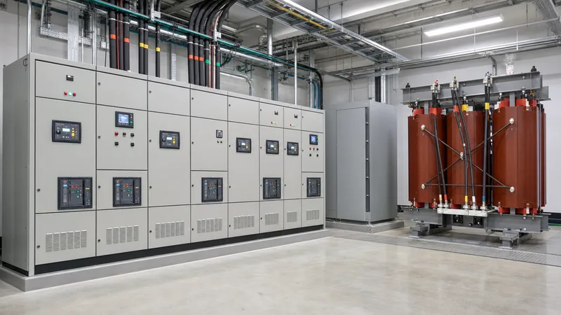
Specialised medium voltage mechanical systems provide the structural containment, thermal dissipation, busbar bracing, and safety interlocks essential for housing high-energy equipment.
Medium-voltage switchgear assemblies, built to IEC 62271-200 or IEEE C37.20.2, are subjected to extreme electrodynamic forces during short-circuit events. Peak currents exert magnetic forces proportional to the square of the peak fault current ($I_p^2$). Consequently, busbar supports, typically moulded from cycloaliphatic epoxy resin, must withstand mechanical shear forces exceeding tens of kilonewtons without micro-fracturing or tracking. Enclosure panels are fabricated from minimum 2.0 mm to 3.0 mm aluzinc or galvanised sheet steel with compartmentalised barriers isolating the busbar, circuit breaker, cable termination, and low-voltage instrument sections.
Thermal management is another critical mechanical challenge. Enclosed dry-type transformers and metal-clad switchgear generate losses that must escape via natural convection (AN) or forced ventilation (AF). If ambient conditions exceed standard limits (e.g., +40 °C per IEC 60076-1 clause 5.1), enclosures require engineered air paths, filtered louvres, or integrated water-air heat exchangers to prevent insulation degradation. Furthermore, Internal Arc Classification (IAC AFLR) dictates that mechanical latches, pressure relief flaps, and rupture ducts direct explosive arc-fault gases upward and away from operating personnel, venting overpressures within milliseconds.
Fault Current Calculation and Equipment Sizing in Medium Voltage Engineering
A core competency in medium voltage engineering is determining prospective symmetrical and asymmetrical short-circuit levels to ensure proper equipment withstand ratings.
Consider an industrial medium voltage electrical substation receiving a 33 kV utility feed with a short-circuit capacity of 750 MVA. The substation employs an oil-immersed step-down transformer feeding an 11 kV distribution board. The transformer parameters are: rated power $S_n = 10\text{ MVA}$, voltage ratio $33/11\text{ kV}$, short-circuit impedance percentage $Z\% = 8.0\%$, and an $X/R$ ratio of 10. To verify the required breaking capacity of downstream 11 kV switchgear, engineers calculate the through-fault contribution per IEC 60909.
- Calculate utility source impedance: Utility impedance on an 11 kV base is determined by $Z_s = \frac{V_{base}^2}{S_{sc}} = \frac{(11\text{ kV})^2}{750\text{ MVA}} = 0.1613\;\Omega$.
- Calculate transformer impedance: Base impedance is $Z_{b} = \frac{V_{base}^2}{S_n} = \frac{(11\text{ kV})^2}{10\text{ MVA}} = 12.1\;\Omega$. The actual transformer impedance is $Z_t = Z_{b} \times \left(\frac{Z\%}{100}\right) = 12.1 \times 0.08 = 0.968\;\Omega$.
- Determine total fault impedance: Neglecting small upstream resistance, $Z_{total} = Z_s + Z_t = 0.1613 + 0.968 = 1.1293\;\Omega$.
- Compute symmetrical short-circuit current ($I_k''$): Using $I_k'' = \frac{c \times V_{base}}{\sqrt{3} \times Z_{total}}$ with voltage factor $c = 1.1$: $I_k'' = \frac{1.1 \times 11,000}{\sqrt{3} \times 1.1293} = 6,183\text{ A} = 6.18\text{ kA}$.
- Determine peak making current ($I_p$): Per IEC 60909-0 clause 4.3, for an $X/R$ ratio around 10, the factor $\kappa \approx 1.74$. Peak current is $I_p = \kappa \times \sqrt{2} \times I_k'' = 1.74 \times 1.4142 \times 6.18\text{ kA} = 15.2\text{ kA}$.
Consequently, the selected 11 kV MV switchgear must feature a symmetrical breaking capacity rated to at least 12.5 kA or 25 kA (the nearest standard rating) and a short-circuit making capacity of no less than 31.5 kA or 63 kA peak. Specifying below these values risks catastrophic breaker failure during an bolted phase-to-phase or phase-to-ground event.
Specification and Factory Inspection Checklist for Medium Voltage Power Solutions
Rigorous procurement specifications ensure that medium voltage power solutions comply with operational, environmental, and thermal performance baselines prior to site delivery.
Specifying engineers must not rely on generic catalogue data. Standard factory tests must be explicitly stated in tender documentation, aligned with IEC 60076 for transformers and IEC 62271 for switchgear assemblies. Critical parameters should be evaluated using formal Factory Acceptance Testing (FAT) protocols, as outlined in technical guides such as power transformer testing procedures. Below is a baseline specification and inspection schedule for medium voltage electrical apparatus:
| Inspection / Parameter | Standard Clause Reference | Engineering Acceptance Criteria | Units / Target Value |
|---|---|---|---|
| Power Frequency Withstand | IEC 60076-3 / IEC 62271-1 | 1 minute applied voltage without flashover or breakdown | 28 kV (for 12 kV) / 70 kV (for 36 kV) |
| Lightning Impulse Withstand (BIL) | IEC 60071-1 Table 2 | Full wave 1.2/50 μs impulse, 3 positive / 3 negative pulses | 75 kV (12 kV class) / 170 kV (36 kV class) |
| Partial Discharge (PD) Test | IEC 60270 / IEC 60076-11 | Measured at 1.3 × or 1.8 × rated phase-to-ground voltage | < 10 pC (cast resin) / < 100 pC (liquid-filled) |
| Temperature Rise Limits | IEC 60076-2 Table 1 | Top oil / average winding rise above 40 °C ambient | 60 K / 65 K (mineral oil, standard class) |
| Internal Arc Containment | IEC 62271-200 Annex A | Indicators do not ignite; doors remain latched; grounding intact | IAC AFLR up to 25 kA / 1.0 s |
| Mechanical Endurance (CB) | IEC 62271-100 Table 14 | Class M2 extended mechanical endurance without maintenance | 10,000 operating cycles |
Prior to shipment, verify all physical clearances between phases and to earth within air-insulated compartments. Minimum clearances in air for an 11 kV system under IEC 60071-2 Table A.1 are typically 120 mm phase-to-earth and phase-to-phase, expanding to 320 mm for 33 kV systems. Any compromise in mechanical clearances requires solid insulating barriers or gas insulation (SF6 or clean-air alternative).
Next steps: specifying and sourcing
Delivering a reliable medium voltage project requires absolute precision in component ratings, footprint constraints, and site operating conditions. When preparing an enquiry, provide prospective vendors with your single-line diagrams (SLD), nominal system voltages, fault capacity at the point of connection, ambient temperature profiles, and desired communication protocols (such as IEC 61850 or Modbus TCP). Our engineering team designs and manufactures high-performance oil-immersed transformers, cast resin units, integrated transformer substations, and complete HV/LV switchgear configured to your exact grid code requirements. Visit our technical portal to request an engineering quotation or discuss specifications with an experienced applications engineer.
Frequently asked questions
What is considered medium voltage electrical?
Under IEC standards, medium voltage electrical systems operate between 1 kV (1,000 V) and 35 kV AC, with some standards extending the classification up to 52 kV. Under North American ANSI/IEEE standards, medium voltage encompasses system operating levels from 1,000 V up to 69,000 V AC.
Why is medium voltage used instead of low voltage for power distribution?
Medium voltage reduces current levels proportionally for a given power demand ($P = \sqrt{3} \times V \times I \times \cos\phi$). Lower current minimises resistive line losses ($I^2R$) and voltage drops over long distances, allowing smaller conductor cross-sections and substantially reducing infrastructure copper costs.
What is the difference between air-insulated and gas-insulated MV switchgear?
Air-insulated switchgear (AIS) uses atmospheric air as the dielectric medium, requiring larger phase-to-phase physical clearances and regular maintenance in dusty environments. Gas-insulated switchgear (GIS) encapsulates primary conductors in hermetically sealed tanks filled with SF6 or technical air, delivering a footprint up to 70% smaller and complete immunity to environmental contaminants.
What is Basic Impulse Insulation Level (BIL) in medium voltage systems?
BIL is a design reference voltage expressed in peak kilovolts that defines the capability of electrical equipment insulation to withstand high-voltage lightning surges and fast-transient switching operations. For instance, standard 11 kV equipment typically requires a BIL rating of 75 kV to 95 kV peak.
How is arc-flash safety handled in medium voltage electrical systems?
Arc-flash safety is achieved through Internal Arc Classification (IAC AFLR) switchgear designs, optical arc-detection relays that trip breakers within 10 to 15 milliseconds, maintenance safety switches, remote racking mechanisms, and coordinated protective relaying that clears faults before dangerous incident energy levels accumulate.
Tags: medium voltage electrical medium voltage electrical systems medium voltage power distribution medium voltage engineering medium voltage power solutions


