Key takeaways
- A core current transformer steps down high primary currents to standard 1 A or 5 A secondary values for protection relays and revenue meters.
- IEC 61869-2 specifies measuring CTs by Instrument Security Factor (ISF) and protection CTs by Accuracy Limit Factor (ALF), such as 5P20 or 10P20.
- Knee-point voltage (Vk) must exceed the total voltage drop across the secondary winding, cable leads, and relay burden during maximum symmetrical fault currents to prevent saturation.
- Never leave an energised current transformer secondary open-circuited, as dangerous kilovolt-level peak potentials will develop across the terminals.
- Selecting magnetic core materials—grain-oriented silicon steel versus high-permeability nickel alloys—directly determines saturation flux density and low-current phase displacement.
Quick answer: A core current transformer is an instrument transformer that scales down primary AC power system currents to safe, standardised secondary values (typically 1 A or 5 A) while isolating secondary relays, meters, and monitoring instruments from high operating voltages. It operates by inducing a proportional magnetic flux within a closed magnetic core surrounding the primary conductor.
In electrical distribution systems, power generation facilities, and industrial substations, the modern ct transformer serves as the critical sensory interface for protective relays and revenue metering devices. Selecting the proper core current transformer requires understanding core magnetic behaviour, accuracy limits under continuous and fault conditions, secondary burden matching, and compliance with IEC 61869-2 or IEEE C57.13 standards. Specifying the incorrect core geometry or saturation rating can result in relay failure during short circuits or significant billing discrepancies in commercial power networks.
Core Current Transformer Operating Principles and Core Materials
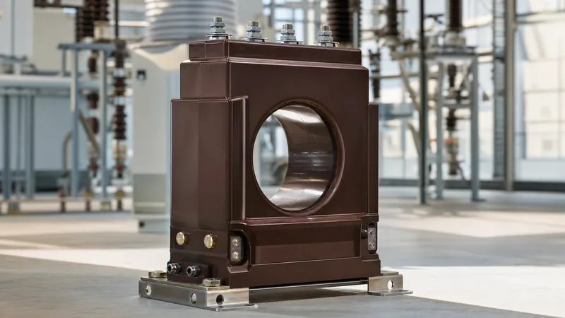
A core current transformer functions on the principle of amp-turn balance governed by Ampère's circuital law and Faraday's law of electromagnetic induction. The primary current $I_p$ flows through $N_p$ turns (often a single pass or busbar through the core aperture), creating a magnetomotive force that produces magnetic flux within the annular core. This flux links with the secondary winding of $N_s$ turns, inducing a secondary current $I_s$ that opposes the primary magnetomotive force. Under ideal conditions, $I_p \times N_p = I_s \times N_s$, meaning secondary current is inversely proportional to the turns ratio.
However, non-ideal behaviour stems from the exciting current $I_e$ required to magnetise the core material and overcome eddy-current and hysteresis losses. The choice of core material dictates the excitation impedance and the saturation flux density ($B_{sat}$):
- Cold-Rolled Grain-Oriented (CRGO) Silicon Steel: The standard core material for protection class current transformers, offering a high saturation flux density between 1.6 T and 1.9 T. CRGO provides mechanical strength and predictable performance under high fault multiples, though it has moderate magnetising losses at low primary current levels.
- Nickel-Iron Alloys (Permalloy / Mumetal): Featuring exceptionally high initial permeability and low coercive force, nickel-iron cores saturate at lower flux densities (0.6 T to 0.8 T). These materials are widely specified for revenue-grade metering cores (Class 0.2S and Class 0.1) where minimal phase displacement and ratio error are required below 5% of rated current.
- Nanocrystalline Alloys: Modern high-efficiency cores combining high permeability with a saturation flux density of approximately 1.2 T. These cores exhibit linear magnetisation curves over wide temperature ranges and are increasingly deployed in high-accuracy measuring units housed within medium-voltage switchgear installations.
Measuring vs Protection Current Transformers: Accuracy and Saturation
Measuring and protection current transformers serve diametrically opposed operational objectives and must not be interchanged.
A measuring ct current transformer protects downstream meters from thermal damage during short circuits by intentionally saturating early. According to IEC 61869-2 clause 5.5, measuring CTs are rated by accuracy class (e.g., Class 0.2, Class 0.5, Class 0.2S) and an Instrument Security Factor (FS, typically FS 5 or FS 10). If a system fault reaches five to ten times rated current, the measuring core saturates, capping secondary current output to prevent meter burnout.
Conversely, a protection class core current transformer must remain linear during extreme short-circuit events to allow protective relays to detect fault magnitudes and calculate directional vector angles. IEC 61869-2 designates protection cores using standard ratings such as 5P20 or 10P20:
- The first number denotes composite error percentage at the rated accuracy limit primary current (5% for 5P, 10% for 10P).
- The letter 'P' indicates protection application.
- The second number is the Accuracy Limit Factor (ALF), defining the multiple of rated primary current up to which the specified accuracy is maintained when driving rated burden (e.g., 20 times rated current).
Under IEEE C57.13 Table 1, protection CTs are classified by their secondary terminal voltage rating preceded by a letter, such as C100, C200, C400, or C800. The letter 'C' indicates that transformer ratio error can be calculated directly because leakage flux within the toroidal core is negligible. The numerical value represents the secondary terminal voltage the CT can deliver at 20 times nominal secondary current without exceeding a 10% composite ratio error.
Knee-Point Voltage Sizing and Worked Burden Calculation
Sizing a protection core current transformer requires calculating the secondary knee-point voltage ($V_k$) to verify that the core will not saturate during maximum symmetrical short-circuit conditions.
Tags: core current transformer current transformers ct transformer ct current transformer current transformer for sale