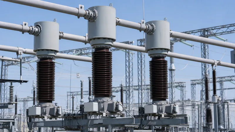
Key takeaways
- A high voltage current transformer scales primary transmission and distribution currents down to galvanically isolated 1 A or 5 A secondary outputs for protection relays and revenue metering.
- The two primary structural configurations are inverted (top-core) designs offering lower leakage reactance and hairpin (bottom-core) designs providing enhanced seismic resilience.
- Never operate a current transformer with an open secondary circuit, as induced peak voltages can exceed 10 kV, presenting severe dielectric flashover and personnel hazards.
- Protection CT sizing requires calculating the knee-point voltage to avoid saturation during asymmetrical through-faults with high system X/R ratios under IEC 61869-2 or IEEE C57.13.
- Factory acceptance testing must verify ratio error, phase displacement, excitation curves, dielectric dissipation factor (tan delta), and secondary winding DC resistance before site energisation.
Quick answer: A high voltage current transformer (HV CT) is an instrument transformer designed to step down power system currents from kilovolt-level circuits (ranging from 36 kV up to 765 kV and above) to standardised, galvanically isolated secondary currents of 1 A or 5 A. This enables safe, accurate operation of protective relays, substation automation units, and revenue metering equipment under both normal and extreme fault conditions.
In modern high-voltage transmission networks and heavy industrial installations, instrument transformers constitute the primary sensory organ of the electrical protection scheme. While a voltage transformer monitors system potential, the high voltage current transformer continuously measures current magnitude and phase angle. Because these units interface directly with high short-circuit levels and extreme transient overvoltages, incorrect selection or improper core sizing can lead to relay misoperation, metering inaccuracies, or catastrophic insulation breakdown. Integrating an HV CT into substations alongside a transmission transformer requires comprehensive understanding of core topography, insulation systems, and dynamic fault performance.
High Voltage Current Transformer Topologies: Inverted vs Hairpin Construction
High voltage current transformers are primarily constructed in two distinct physical topologies: the inverted (top-core) configuration and the traditional hairpin (bottom-core or tank) configuration. The choice between these designs directly influences dynamic short-circuit withstand, centre of gravity, and transient response.
In the inverted design, the secondary cores and windings are located inside the top expansion head, directly adjacent to the high-voltage conductor. The primary conductor is short and straight, passing through the annular cores. This geometry minimises primary winding resistance and leakage inductance, giving the inverted high voltage ct superior thermal and dynamic short-circuit ratings (up to 63 kA for 3 seconds). However, positioning the active iron and copper mass at the top of a tall composite or porcelain insulator raises the mechanical centre of gravity, requiring robust mechanical design in regions with high seismic activity.
Conversely, the hairpin design places the secondary cores and windings inside the grounded bottom tank. The primary conductor forms a long, insulated U-shape loop that extends from the top terminal down through the cores and back up. This arrangement lowers the centre of gravity and provides excellent seismic performance. The trade-off lies in the longer primary path, which generates higher internal electrical losses, requires more insulation material, and increases vulnerability to internal mechanical stresses during high-amplitude short-circuit events. Both configurations utilise either mineral oil-impregnated paper (OIP) or sulfur hexafluoride (SF6) gas as the internal dielectric medium, hermetically sealed with metallic bellows or gas-density monitoring systems.
Accuracy Classes and Burden Specifications Under IEC and IEEE Standards
Accuracy classification determines how faithfully a current transformer reproduces the primary current waveform across steady-state operational loads and dynamic system faults. Instrument transformers are divided into metering cores, which require extreme precision near nominal current and saturation at low overcurrents to protect instruments, and protection cores, which must remain linear under multi-fold fault currents.
Under IEC 61869-2 (which superseded IEC 60044-1), metering classes such as 0.2, 0.2S, 0.5, and 0.5S define maximum permissible ratio and phase errors from 1% to 120% of rated current ($I_n$). The designation "S" denotes special calibration for extended range accuracy down to 1% of $I_n$, critical for boundary tariff metering. Protection classes are typically designated as 5P or 10P followed by an accuracy limit factor (ALF), such as 5P20. A 5P20 core maintains a composite error under 5% at 20 times the rated symmetrical current when connected to its rated burden.
In North American practice governed by IEEE C57.13 Table 5, relaying cores carry classifications such as C400 or C800. The letter "C" indicates that transformer ratio error can be calculated (low leakage reactance), and the number represents the secondary terminal voltage the CT can deliver at 20 times rated secondary current (typically 100 A on a 5 A base) with less than a 10% ratio correction error. Sizing engineers must match the external secondary loop impedance—comprising relay input circuitry, control cables, and junction terminals—against the rated burden (expressed in volt-amperes or ohms) to prevent early core saturation during faults managed by a substation protection scheme.
| Standard | Core Application | Class Designation | Max Ratio Error (%) | Primary Operating Limit |
|---|---|---|---|---|
| IEC 61869-2 | Revenue Metering | Class 0.2S | ±0.2% | 100% to 120% $I_n$ (holds to 1% $I_n$) |
| IEC 61869-2 | Standard Metering | Class 0.5 | ±0.5% | 100% to 120% $I_n$ |
| IEC 61869-2 | Relay Protection | 5P20 | ±1.0% (5% composite) | 20 × $I_n$ at rated burden |
| IEC 61869-2 | Special Relaying | Class PX / PR | Calculated knee-point | Defined by excitation curve ($V_k$) |
| IEEE C57.13 | Revenue Metering | 0.3 B-0.5 | ±0.3% | 100% to 200% rating factor |
| IEEE C57.13 | Relay Protection | Class C400 | ±10.0% | 20 × nominal (100 A on 5 A tap) |
Worked Calculation: Knee-Point Voltage and Burden Sizing for Relay Protection
Calculating the secondary knee-point voltage ensures that a high voltage current transformer does not saturate during peak asymmetrical fault conditions, which could otherwise blindingly block or destabilise differential relaying schemes.
Consider an electrical substation where a 110 kV high voltage current transformer feeds a unit protection relay under the following real-world parameters:
- Maximum symmetrical prospective three-phase fault current ($I_f$): 31,500 A
- CT rated turns ratio ($K_t$): 2000/1 A ($I_{pri} = 2000\text{ A}$, $I_{sec} = 1\text{ A}$)
- CT secondary internal winding resistance ($R_{ct}$): 3.8 Ω at 75 °C
- Single-conductor secondary cable run (lead) length: 150 metres
- Secondary cable cross-section: 4.0 mm² copper (resistance per unit length: 4.61 mΩ/m at 75 °C)
- Relay internal input impedance ($R_r$): 0.1 Ω
- System primary electrical time constant / DC offset factor ($K_{td}$): 1.5
First, calculate the total secondary loop resistance ($R_{loop}$), accounting for the round-trip distance (go and return):
$$R_{lead} = 2 \times 150\text{ m} \times 0.00461\ \Omega/\text{m} = 1.383\ \Omega$$
$$R_{total} = R_{ct} + R_{lead} + R_r = 3.8 + 1.383 + 0.1 = 5.283\ \Omega$$
Next, determine the maximum secondary fault current under symmetrical conditions ($I_{f,sec}$):
$$I_{f,sec} = \frac{I_f}{K_t} = \frac{31500\text{ A}}{2000} = 15.75\text{ A}$$
To guarantee stability under transient DC offsets, apply the transient factor ($K_{td} = 1.5$) to determine the minimum required knee-point voltage ($V_k$) according to the standard relationship:
$$V_k \ge K_{td} \times I_{f,sec} \times R_{total}$$
$$V_k \ge 1.5 \times 15.75\text{ A} \times 5.283\ \Omega = 124.81\text{ V}$$
If specifying a Class PX core under IEC 61869-2 clause 5.6.201, the engineer should round up and specify an excitation knee-point voltage ($V_k$) of at least 135 V with a maximum magnetising current ($I_e$) of 20 mA at $V_k / 2$. If using an existing CT with a measured $V_k$ of only 100 V, the core would saturate during the initial DC component of the fault, potentially causing false tripping or tripping delays on a critical line or transformer protection scheme.
Installation, Earthing, and Open-Circuit Hazards of a High Voltage CT
Operating a high voltage current transformer requires strict adherence to isolation rules and secondary circuit earthing to eliminate catastrophic voltage hazards.
The foremost hazard associated with any energised high voltage ct is an open-circuited secondary winding. Under normal closed-loop conditions, the secondary current produces a counter-magnetomotive force (MMF) that neutralises nearly all of the primary MMF, leaving only a tiny resultant flux to magnetise the iron core. If the secondary circuit is opened while primary current flows, this balancing secondary MMF drops instantly to zero. The entire primary current becomes magnetising current, forcing the iron core into deep magnetic saturation.
As the primary alternating current passes through zero, the flux collapses and reverses at an extremely rapid rate ($d\Phi/dt$). This rate of change induces lethal, narrow voltage spikes across the open secondary terminals that routinely reach 5 kV to 15 kV peak. These voltages inevitably flash over terminal blocks, puncture internal secondary insulation, ignite control wiring, and present fatal shock hazards to substation personnel. For this reason, secondary wiring paths must include shorting terminal blocks that allow maintenance personnel to mechanically short the CT secondary before disconnecting test leads or relays.
Equally critical is strict single-point earthing. Every active current transformer secondary circuit must be bonded to the substation ground grid at exactly one point—typically at the terminal cabinet in the relay control room. If a circuit is grounded at multiple points, stray earth currents circulating between disparate grid potentials can induce spurious currents in the measurement loop, degrading metering accuracy and causing differential protection relays to operate spuriously.
Factory Acceptance Testing and Routine Diagnostic Procedures
Factory acceptance testing (FAT) for a high voltage current transformer validates insulation integrity and magnetic performance before site delivery, in accordance with IEC 61869-1, IEC 61869-2, and IEEE C57.13 requirements.
- Insulation Resistance and Tan Delta (Power Factor) Testing: Apply high-voltage test potential (typically 10 kV) between primary windings and earth, and between primary and secondary windings. In oil-immersed units, dielectric dissipation factor ($\tan \delta$) must not exceed 0.5% at 20 °C. Elevated dissipation factors signal moisture ingress or paper degradation.
- Secondary Winding Resistance Measurement: Measure the direct-current resistance of each secondary tap using a calibrated micro-ohmmeter, correcting the recorded values to a reference temperature of 75 °C. This data is critical for differential protection stability calculations.
- Excitation (Magnetisation) Curve Verification: Progressively inject AC voltage into the secondary winding while the primary remains open-circuit. Record the magnetising current up to and beyond the knee-point, confirming compliance with the specified knee-point voltage ($V_k$) and saturation characteristics.
- Ratio and Phase Angle Error Verification: Using precision reference current standards and bridge sets, verify current ratio error and phase displacement across the entire operating range from 1% to 120% of rated current for metering cores, and at rated accuracy limit factor for protection cores.
- Inter-Turn Overvoltage Withstand Test: Energise the primary winding with rated power frequency current while the secondary circuit is open-circuited for 60 seconds (or apply test voltage equivalent to rated withstand across secondary terminals), verifying that the turn-to-turn insulation does not track or fail under induced transients.
Next steps: specifying and sourcing
When preparing an inquiry or technical schedule for a high voltage current transformer, furnish full operating criteria to the engineering team: nominal and maximum system voltages, basic insulation level (BIL), rated continuous primary current, short-time thermal current ($I_{th}$ for 1 or 3 seconds), environmental ambient parameters, seismic zone ratings, creepage distance, and exact burden and accuracy classes for all individual secondary cores. Explore our range of high-performance power transformers and integrated transformer substations designed to complete your high-voltage grid infrastructure. To discuss technical specifications or request a formal commercial proposal, submit your project single-line diagrams through our quotation inquiry page or connect directly with our application engineers via the contact office.
Frequently asked questions
What happens if a high voltage current transformer secondary is left open?
Leaving the secondary circuit of an energised high voltage current transformer open eliminates the counter-opposing magnetic field, driving the iron core into deep saturation. The rapid magnetic flux reversal induces dangerous peak voltages exceeding 5 kV across the secondary terminals, causing dielectric puncture, catastrophic arc flashes, and severe life-safety hazards.
What is the difference between an inverted CT and a bottom-core CT?
An inverted CT places its secondary cores and windings inside the top expansion head, featuring a short primary conductor that yields low leakage impedance and high short-circuit capability. A bottom-core or hairpin CT houses its cores inside the grounded base tank, lowering the physical centre of gravity for superior seismic performance.
Why are different CT cores used for protection and metering?
Metering cores are engineered with easily saturable magnetic alloys to achieve high measurement precision up to 120% load while saturating at low fault currents to safeguard connected meters. Protection cores use wider magnetic ranges to remain strictly linear during severe 20-fold short-circuit currents, ensuring protective relays receive true waveforms.
How is the knee-point voltage of a high voltage CT defined?
Under IEC standards, the knee-point voltage is the point on the secondary excitation curve where a 10% increase in applied root-mean-square sinusoidal voltage increases the magnetising current by 50%. It represents the boundary where the core leaves its linear region and begins magnetic saturation.
Why must a current transformer secondary circuit have only one earthing point?
A current transformer secondary loop must be grounded at exactly one physical point to prevent multiple earth paths from creating circulating ground currents. Multiple ground connections allow substation grid potential differences to inject spurious error currents into the measurement loop, causing protective relay false-tripping.
Tags: high voltage current transformer high voltage ct instrument transformer substation protection transformer testing


