Key takeaways
- A transmission transformer interfaces generation and transmission grids, operating at primary voltages from 66 kV to 765 kV to minimise I²R line losses.
- System impedance (%Z) directly governs short-circuit fault levels and system stability, typically ranging between 10% and 18% on large bulk-power units.
- Basic Impulse Insulation Level (BIL) ratings per IEC 60076-3 or IEEE C57.12.00 determine transformer dielectric withstand against lightning and switching surges.
- Cooling stages (ONAN/ONAF/ODAF) expand effective thermal capacity by up to 67%, governed by winding hot-spot limits of 118°C under rated maximum emergency loading.
- Factory acceptance testing requires routine loss measurement, dielectric tests, and partial discharge screening to ensure failure rates below 0.5% over a 40-year design life.
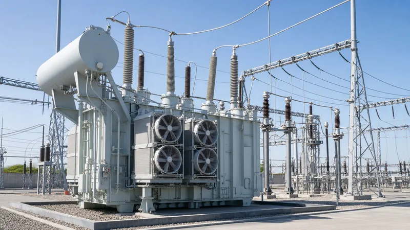
Quick answer: A transmission transformer is a heavy-duty power transformer designed to step electrical voltage up or down between power generation assets, bulk transmission lines, and regional transmission substations, typically operating between 66 kV and 765 kV with continuous ratings from 40 MVA to over 1,000 MVA.
In alternating-current power grids, bulk electricity transmission relies on high system voltages to limit thermal losses over long geographical distances. A power transmission transformer represents the most critical, capital-intensive node in this network. Operating continuously under arduous dielectric, thermal, and electrodynamic stresses, these assets must combine high electrical efficiency—frequently exceeding 99.6%—with mechanical robustness capable of surviving direct through-fault events up to 40 kA symmetrical short-circuit current.
For utility transmission engineers, substation consultants, and Engineering, Procurement, and Construction (EPC) contractors, specifying a transmission-class unit demands an uncompromising balance between Basic Impulse Insulation Level (BIL), short-circuit impedance (%Z), thermal loss evaluation, and on-load tap-changer (OLTC) regulation. This comprehensive guide details the design criteria, grid interaction physics, vector architectures, loss economics, and factory verification routines required to procure and operate high-reliability transmission units.
What is a transmission transformer in modern grid architecture?
A transmission transformer is an electrical machine engineered to transition bulk energy between transmission voltage levels or from central power stations into the high-voltage transmission grid. Unlike distribution units that feed local consumer loads at medium and low voltages, a power transmission transformer operates at the regional transmission backbone level (typically 110 kV, 132 kV, 220 kV, 275 kV, 400 kV, and 500 kV in IEC territories, or 115 kV to 765 kV in IEEE jurisdictions).
Within modern grid topologies, transmission-class units fulfill three primary functional roles across the power system:
- Generator Step-Up (GSU) Transformers: Located directly adjacent to power stations (thermal, hydro, nuclear, or utility-scale renewables), GSUs step up generation voltages (commonly 11 kV to 24 kV) to transmission network levels (such as 220 kV or 400 kV), enabling bulk power export with minimal resistive dissipation.
- System Intertie and Auto-Transformers: Positioned at the junctions of different transmission networks (for example, stepping 400 kV down to 220 kV or 132 kV), these units facilitate cross-regional power exchanges. Auto-transformer topologies are standard when the ratio of high-to-low voltage is less than 3:1, providing substantial cost, weight, and loss reductions over separate-winding units.
- Transmission Substation Step-Down Transformers: Installed at the periphery of urban or industrial load centres, these units reduce bulk transmission voltages to sub-transmission or distribution primary voltages (typically 33 kV, 66 kV, or 110 kV).
Because transmission systems carry hundreds of megawatts through single transformer bays, unexpected outages induce severe grid redispatch penalties and potential blackout conditions. Consequently, design safety margins, material purity, and condition monitoring systems are far more stringent than those applied to distribution-class equipment.
How transmission lines and transformers interact across high-voltage networks
The technical interaction between transmission lines and transformers dictates system voltage stability, reactive power balance, and fault clearance dynamics across high-voltage networks. A long overhead line behaves as a distributed parameters network exhibiting series inductance and shunt capacitance. When high-voltage lines operate at light load, line capacitance generates surplus reactive power, causing the receiving-end voltage to rise above the sending-end voltage—a phenomenon known as the Ferranti effect.
Transmission transformers mitigate or compound these line interactions depending on their impedance configuration and tap-changing capability:
- Reactive Power Compensation: Transformers consume reactive power ($Q = I^2 X_T$) proportional to the square of the throughput current and their internal leakage reactance ($X_T$). Under peak transmission loading, transformer reactive absorption accelerates line voltage drop, requiring co-located capacitor banks, static VAR compensators (SVCs), or STATCOM systems to maintain bus voltages within statutory tolerances (typically $\pm 5\%$ steady-state).
- Impedance Coordination and Power Flow: In meshed transmission networks, power splits inversely proportional to branch impedances. If a transformer bank presents an inappropriately low leakage reactance relative to parallel lines, it experiences severe continuous overloading. Conversely, high impedance curtails transfer capacity and lowers the transient stability margin of connected generation.
- Switching Transients and Resonance: Energising long unloaded transmission lines terminates in steep-front travelling waves that enter transformer bushings. Without surge arresters and properly graded winding electrostatic shielding, these high-frequency reflections concentrate dielectric stress across the first 10% of the transformer's line-end winding turns, causing inter-turn insulation puncture.
- Zero-Sequence Current Paths: Asymmetrical line-to-earth faults require dedicated zero-sequence return paths. The earthing arrangements of transmission transformers dictate the magnitude of earth-fault currents and provide the physical reference that stabilises neutral point voltages during single-phase line tripping.
Key engineering specifications for power systems transformers
Specifying power systems transformers requires precise harmonisation of nominal power, voltage classes, system insulation coordinates, and short-circuit withstand parameters according to standards such as IEC 60076 or IEEE C57.12.00. The foundational rating of a transmission-class unit is defined across its continuous MVA capacity, winding connection, and BIL rating.
System engineers must establish clear parameters across several core electrical characteristics:
- Rated Power (MVA) and Overload Profiles: Defined as base cooling rating (ONAN) and staged forced-cooling ratings (e.g., ONAF1, ONAF2, or ODAF). IEC 60076-7 provides loading guides for oil-immersed transformers, defining permissible cyclic and emergency loading above nameplate rating without exceeding hot-spot limits.
- Voltage Ratio and Tapping Range: Specified as primary nominal, secondary nominal, and tertiary nominal (if applicable). On-load tap changers are typically integrated into the neutral end of high-voltage star windings to manage $\pm 10\%$ to $\pm 15\%$ system variations in discrete steps of 1.25% to 1.67%.
- Basic Impulse Insulation Level (BIL) and Switching Impulse (SIL): For systems of 220 kV and above, switching impulses frequently govern insulation clearance rather than lightning impulses. A 400 kV transmission transformer typically demands a lightning impulse withstand of 1,425 kV (peak) and a switching impulse withstand of 1,050 kV (peak) in accordance with IEC 60076-3.
- Short-Circuit Impedance (%Z): Transmission transformers are engineered with high leakage impedance—typically 12% to 18% on their base MVA rating—to restrict secondary short-circuit currents within the breaking ratings of downstream circuit breakers (commonly 40 kA or 50 kA).
- Sound Power Levels: Due to strict environmental regulations near residential zones, sound power levels must be controlled using reduced core flux densities, anti-vibration pad isolation, and low-speed condenser fans, often targeting levels below 65 dB(A) at 2 metres.
Core, winding, and insulation design in transmission-class units
Internal design decisions determine whether a transmission transformer achieves its operational life expectancy of 35 to 50 years under continuous electrical and thermal stress. The physical structure comprises a laminated magnetic core, interleaved high-voltage windings, and a multi-barrier oil-paper dielectric system. Detailed understanding of these structures can be explored further in the technical guide on transformers internal components.
At high transmission voltages, electrical clearances and electromagnetic force distribution dominate internal geometry:
- Magnetic Core Architecture: Fabricated from high-permeability, cold-rolled grain-oriented (CRGO) silicon steel or laser-scribed domain-refined steel laminations (typically 0.23 mm to 0.27 mm thickness). Mitred step-lap joints minimise eddy current circulating paths and suppress magnetising inrush current harmonics. Three-phase units employ either three-limb or five-limb configurations; five-limb designs are required on large auto-transformers to reduce total transport height and provide a return path for zero-sequence flux.
- Winding Configurations: High-voltage windings (110 kV to 500 kV) rarely use continuous disc configurations without capacitive grading. Instead, manufacturers implement interleaved disc or shielded disc windings. By cross-connecting conductors between adjacent discs, the series capacitance ($C_s$) of the winding is increased by a factor of 10 to 15 relative to its shunt capacitance to earth ($C_g$). This high $C_s / C_g$ ratio ensures uniform initial voltage distribution during fast-front lightning surges, eliminating localized stress concentrations.
- Solid and Liquid Insulation: Insulation relies on high-density, thermally upgraded cellulose pressboard cylinders, angle rings, and oil ducts impregnated with high-grade inhibited mineral insulating oil (meeting IEC 60296) or synthetic ester fluids. Barrier systems partition long oil gaps into smaller segments, exploiting the "volume effect" where breakdown strength increases substantially as individual oil volume decreases.
- Mechanical Clamping and Short-Circuit Rigidity: During external faults, electromagnetic forces scale with the square of the peak fault current ($I_{peak}^2$). Radial forces attempt to burst outer windings and crush inner windings, while axial forces cause disc tilting and core clamping displacement. High-tensile tie rods and pre-stressed clamping rings maintain continuous compressive force across the winding stacks throughout the operational lifespan.
Vector groups, phase shifting, and system grounding configurations
Vector group selection dictates the phase displacement between primary and secondary line voltages, zero-sequence fault current circulation, and compatibility with parallel network branches. Selecting the appropriate connection requires deep familiarity with international network standards, as explained in our detailed analysis of transformer vector groups explained.
For high-voltage transmission units, three winding configurations dominate utility installations:
- YNd11 or YNd1 (Star-Grounded Primary, Delta Secondary): Standard for Generator Step-Up applications. The grounded-star connection on the transmission high-voltage side provides a solidly earthed neutral to limit overvoltages during line-to-earth faults, while the delta connection on the generator side traps third-harmonic magnetising currents and prevents zero-sequence currents from passing between networks.
- YNyn0 with Tertiary Delta (Star-Grounded / Star-Grounded): Standard for transmission sub-stations where both HV and MV systems require grounded neutrals for protective relay operation. Because a YNyn connection offers no closed path for third-harmonic currents, an unloaded or station-service delta-connected tertiary winding (typically rated at 15% to 33% of the main transformer MVA) is embedded within the core window. This delta tertiary balances phase voltages under unbalanced single-phase loads and suppresses circulating harmonic voltages.
- Auto-Transformer (YNauto0 with Tertiary Delta): The most economical design for tying high-voltage systems with small voltage differentials (e.g., 400/220 kV or 220/110 kV). The primary and secondary windings share a common winding section, drastically reducing mass, footprint, and internal resistance. A delta tertiary winding remains mandatory to suppress zero-sequence impedance and provide auxiliary substation power.
Thermal management, losses, and total cost of ownership
Total Cost of Ownership (TCO) analysis governs the commercial selection of a transmission transformer, where the capitalised cost of electrical losses over 30 years often exceeds the initial purchase price. System operators evaluate transformer bids using net present value formulas that assign financial penalties to no-load losses (core loss) and load losses (winding copper loss), as examined in our guide to transformer losses and total cost of ownership.
The capitalised cost is calculated via the standard formula:
$$\text{TCO} = C_{purchase} + (A \times P_0) + (B \times P_k)$$
Where $C_{purchase}$ is the landed unit price, $P_0$ is guaranteed no-load loss in kilowatts, $P_k$ is guaranteed load loss at rated MVA and reference temperature (typically 75°C), and $A$ and $B$ are capitalization coefficients reflecting utility electricity generation costs, discount rates, and operational capacity factors. Typical utility values range from $4,000 to $10,000 per kW for $A$, and $1,500 to $4,000 per kW for $B$.
Thermal performance directly influences asset longevity. Under IEC 60076-2, standard limits stipulate a top-oil temperature rise of 60 K and an average winding temperature rise of 65 K above ambient. The table below outlines standard cooling designations applied to transmission-class transformers:
| Cooling Class | Circulation Medium (Internal) | Circulation Method (Internal) | Cooling Medium (External) | Cooling Mechanism (External) | Typical Application Capacity |
|---|---|---|---|---|---|
| ONAN | Mineral Oil | Natural Convection | Air | Natural Convection | Base rating (up to 60% of maximum MVA) |
| ONAF | Mineral Oil | Natural Convection | Air | Forced (Electric Fans) | Medium peak capacity (up to 80% maximum MVA) |
| OFAF | Mineral Oil | Forced (Pumps, non-directed) | Air | Forced (Blowers/Fans) | Bulk power units (100–300 MVA) |
| ODAF | Mineral Oil | Forced Directed (Pipes into coils) | Air | Forced (Blowers/Fans) | High-density GSUs (>250 MVA, compact footprint) |
| OFWF / ODWF | Mineral Oil | Forced (Directed or Non-directed) | Water | Water-Cooled Heat Exchangers | Underground hydro stations, offshore platforms |
Factory acceptance testing and commissioning protocols
Factory Acceptance Testing (FAT) validates the mechanical integrity, dielectric capability, and loss guarantees of a newly fabricated transmission transformer prior to transport. Because field repairs on high-voltage transmission units are prohibitively costly, FAT protocols follow rigorous regimes defined in IEC 60076-1 through 60076-5. For comprehensive testing walk-throughs, refer to our operational manual on how to test a transformer.
The verification sequence follows a strict progression of non-destructive screening, dielectric proof tests, and thermal measurements:
- Routine Dielectric and Ratio Checks: Verification of voltage turns ratio on all tap positions, winding resistance measurement using high-precision micro-ohmmeters, and vector group phase-angle confirmation. Insulation resistance (IR) and dielectric dissipation factor ($ an \delta$) establish baseline values for the bushings and winding insulation structures.
- Loss and Impedance Measurement: No-load losses ($P_0$) and exciting current are measured at 90%, 100%, and 110% of rated voltage using high-precision power analyser systems. Load losses ($P_k$) and short-circuit impedance (%Z) are evaluated at rated current with short-circuited secondary terminals, corrected mathematically to reference operating temperature (75°C).
- Dielectric Withstand Testing: Includes separate source AC withstand (power frequency applied between windings and earth), short-duration induced AC withstand (ACSD), and long-duration induced AC voltage testing with Partial Discharge (PD) measurement (ACLD). Per IEC 60076-3, continuous PD levels must remain below 100 pC at $1.58 U_m / \sqrt{3}$ throughout the testing window.
- Impulse Tests: Full-wave and chopped-wave lightning impulse tests applied to line and neutral bushings (e.g., 1.2/50 $\mu\text{s}$ wave shape) verify winding surge distribution. Switching impulse tests (250/2500 $\mu\text{s}$) verify internal clearances and external air clearances under system transient conditions.
- Temperature Rise Test: Carried out on the first unit of a design series to confirm that top-oil, average winding, and hot-spot temperatures do not exceed contract specifications under maximum cooling operation. Dissolved Gas Analysis (DGA) is conducted on oil samples drawn before and after the heat run to verify absence of localised thermal hot-spots.
- Frequency Response Analysis (SFRA): Establishes a definitive baseline electromagnetic transfer signature (10 Hz to 2 MHz) prior to shipment. A post-transport SFRA test at the destination site verifies that transit impacts have not displaced core limbs, shifted clamping structures, or distorted winding geometries.
Next steps: specifying and sourcing
Procuring a high-voltage transmission transformer requires unambiguous tender technical schedules detailing base MVA, maximum stage MVA, primary and secondary system voltages, insulation levels (BIL/SIL), impedance tolerances, and loss evaluation formulas ($A$ and $B$ values). Our engineering team designs and manufactures bespoke, fully compliant transmission units up to 110 kV and 31,500 kVA, alongside high-capacity utility equipment built to IEC and IEEE standards. Explore our high-voltage portfolio under power transformer and heavy-duty oil-immersed transformer solutions. To submit tender specifications or request a detailed engineering design consultation, contact our transmission specialists directly via our transformer quotation portal.
Frequently asked questions
What is the primary difference between a transmission transformer and a distribution transformer?
A transmission transformer operates at high voltages (66 kV to 765 kV) to transfer bulk power across regions, designed with high impedance and continuous ratings exceeding 40 MVA. A distribution transformer steps medium voltage (11 kV to 33 kV) down to consumer-level utilization voltages (400 V / 230 V) with lower impedance and lower overall capacity.
Why are auto-transformers widely used in transmission networks?
Auto-transformers share a common winding for primary and secondary circuits, making them significantly smaller, lighter, cheaper, and more efficient than separate-winding units when voltage ratios are under 3:1. They provide optimal power transfer between adjacent high-voltage transmission grids, such as 400 kV to 220 kV networks.
What role does transformer impedance (%Z) play in transmission system safety?
Transformer impedance limits the magnitude of short-circuit fault current that can pass into downstream switchgear and cables during a line fault. Typical transmission values range from 10% to 18%, balancing short-circuit protection against acceptable voltage regulation and system reactive power consumption.
Why is an on-load tap changer (OLTC) required on a transmission transformer?
An on-load tap changer adjusts the transformer turns ratio while carrying full load current, maintaining steady secondary bus voltages despite fluctuations in grid demand and upstream voltage drops. In transmission networks, OLTCs typically provide $\pm 10\%$ to $\pm 15\%$ voltage variation in steps of approximately 1.25%.
What causes partial discharge in high-voltage transmission transformers?
Partial discharge occurs when localized electrical stress exceeds the dielectric breakdown strength of small voids, gas bubbles, or moisture pockets within the solid cellulose or liquid mineral oil insulation. Left unaddressed, ongoing partial discharge progressively degrades surrounding insulation, eventually leading to catastrophic phase-to-earth dielectric breakdown.
Tags: transmission transformer power transmission transformer power systems transformers transmission lines and transformers high-voltage substation


