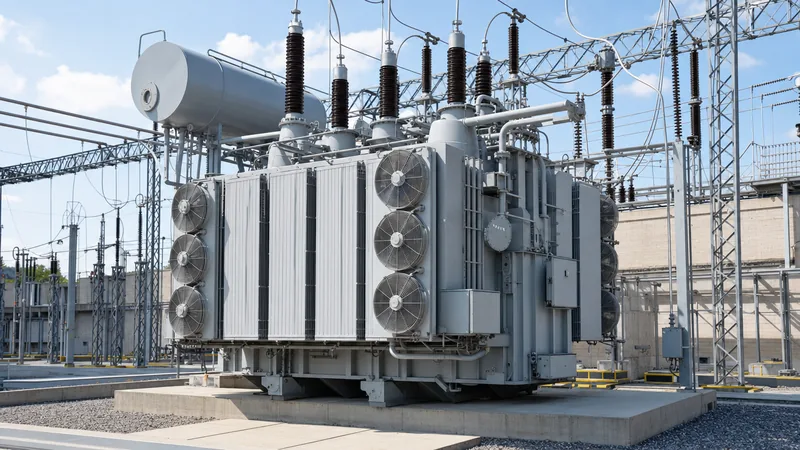
Key takeaways
- A main transformer serves as the critical primary energy exchange node between transmission grids and distribution systems or bulk industrial loads.
- Differential protection (ANSI 87T) paired with restricted earth fault protection (ANSI 64R) forms the primary electrical safety barrier for internal phase-to-phase and ground faults.
- Per IEC 60076-5 clause 4, transformer impedance must balance fault-level mitigation on secondary switchgear with acceptable bus voltage drop under full load.
- Factory acceptance testing per IEC 60076-3 mandates lightning impulse, power-frequency withstand, and dissolved gas analysis before equipment dispatch.
- Physical containment, automatic water-deluge or synthetic-ester alternatives, and blast deflection walls are required by NFPA 850 for fire mitigation on high-capacity units.
Quick answer: A main transformer is the primary, large-capacity power transformer within an electrical substation responsible for stepping transmission voltages down to intermediate distribution levels, or generator voltages up to the bulk transmission grid. It incorporates dedicated differential protection, mechanical fault gas relays, and automated on-load tap changers to maintain network voltage stability and system reliability.
In industrial plants, utility bulk-supply points, and generation facilities, the main transformer represents the single most critical asset in the electrical supply network. Failure of this primary node interrupts downstream power distribution, risking extended commercial downtime and severe equipment damage. Selecting, protecting, and operating high-voltage transformer assets requires an engineering approach founded on international design codes, precise fault calculations, and coordinated physical safety barriers.
What Is a Main Transformer and Its Core Substation Function?
A main transformer operates as the central electrical intertie linking different voltage tiers within a utility network, industrial complex, or power generation facility. Unlike auxiliary or local service units, the main transformer handles the total facility load demand, stepping bulk supply voltages—typically ranging from 66 kV to 400 kV—down to medium-voltage distribution buses such as 11 kV, 22 kV, or 33 kV. In thermal, hydro, and renewable power stations, this unit functions in reverse as a generator step-up unit, lifting generating output voltages directly to transmission grid levels.
Because total operational reliability hinges on this asset, engineers design the surrounding installation with rigorous redundancy, selecting primary power transformer units configured for heavy continuous cyclic loading per IEC 60076-7. The asset interfaces directly with high-voltage gas-insulated or air-insulated switchgear on the primary side and incoming switchgear lineups on the secondary side. Auxiliary oil-immersed transformer units supply local substation station service loads, but the primary asset bears the full dynamic thermal and mechanical stresses imposed by through-fault currents across downstream networks.
Primary Safety and Protection Schemes for Main Transformer Units
Protective relaying for large transformer equipment relies on dual-channel architectures that separate internal unit faults from external system disturbances. The primary protection scheme is the percentage-restrained differential relay (ANSI 87T), which compares vector-corrected currents entering the high-voltage bushings against currents leaving the low-voltage bushings per IEEE C57.13. Dual-slope restraint characteristics prevent nuisance tripping during high-magnitude external through-faults accompanied by current transformer saturation or magnetising inrush.
For grounded wye windings, engineers deploy restricted earth fault protection (ANSI 64R) using either high-impedance or numerical low-impedance algorithms to detect ground faults close to the winding neutral where phase differential sensitivity diminishes. Supplementary electrical protection includes directional overcurrent (ANSI 67), backup time-delay overcurrent (ANSI 51/51N), and overexcitation relays (ANSI 24) to track volts-per-hertz ratios and prevent core saturation. A comprehensive overview of primary and secondary relay arrangements is detailed in our transformer protection engineering guide.
Mechanical detection instruments provide autonomous trips independent of secondary current circuits:
- Buchholz Relay (ANSI 63): Installed in the pipework between the main tank and conservator to catch slow gas accumulation from partial discharge (alarm) and sudden oil surges from arcing (trip).
- Pressure Relief Device (PRD): Spring-loaded mechanical diaphragms fitted with microswitches that snap open within milliseconds when internal dynamic pressure spikes exceed 70 kPa to 100 kPa.
- Rapid Pressure Rise Relay (ANSI 63X): Monitors the rate of tank pressure change to trip lockout relays before mechanical tank rupture occurs.
- Thermal Replica Relays (ANSI 49): Combine top-oil temperature thermometers and winding thermal mimics fed by bushing current transformers to manage cooling stages and initiate emergency load shed.
Fire Separation and Physical Risk Mitigation
Physical safety measures must contain mineral oil catastrophic failures to prevent adjacent switchgear destruction and structural building collapse. Mineral oil possesses a flash point between 135°C and 165°C and a fire point exceeding 170°C; large units often contain more than 20,000 litres of combustible liquid. Under high-energy arc events, oil vapour ignites rapidly, necessitating comprehensive passive and active barriers detailed in our transformer fire protection system guide.
Per NFPA 850 recommendations and IEC 61936-1 guidelines, outdoor oil-filled units requiring more than 1,000 litres of oil must be sited with distinct spatial clearances or protective fire barriers:
- Spatial Clearance: Outdoor units must be separated from exposed building walls and adjacent electrical equipment by 7.6 to 15 metres depending on oil volume, or separated by a two-hour fire-rated barrier wall extending at least 0.61 metres above the top of the bushings and conservator.
- Oil Containment: Concrete catch basins beneath the tank must hold 100% of the transformer liquid capacity plus a minimum allowance for ten minutes of fire-deluge water (typically 110% to 120% total volume), equipped with flame-arresting crushed rock (30 mm to 50 mm stone layer).
- Active Suppression: Automatic high-velocity water spray systems engineered to deliver a minimum discharge density of 10.2 L/min/m² over all exterior transformer surfaces, or fixed nitrogen-injection fire-fighting systems (NIFFS) that depressurise and agitate the oil pool with inert gas.
Main Transformer Sizing and Impedance Calculation
Determining the rated capacity and short-circuit impedance of a main transformer requires balancing steady-state continuous thermal demand against downstream switchgear breaking capacities. Sizing begins by calculating the combined peak apparent power demand, accounting for simultaneous diversity factors, power factor corrections, and future expansion reserves.
Consider an industrial manufacturing facility with a total connected real load ($P$) of 24 MW at a lagging operating power factor ($\cos\phi$) of 0.88, with an expected future facility growth allowance of 20% over a ten-year planning horizon:
1. Calculate base apparent load demand ($S_{base}$):
$$S_{base} = \frac{P}{\cos\phi} = \frac{24\text{ MW}}{0.88} = 27.27\text{ MVA}$$
2. Apply the 20% future capacity margin ($k_g = 1.20$):
$$S_{required} = 27.27\text{ MVA} \times 1.20 = 32.72\text{ MVA}$$
Select a standard nominal rating of 31.5/40 MVA ONAN/ONAF per IEC 60076-1. Next, determine the required percent impedance ($%Z$) to restrict the maximum low-voltage symmetrical fault current ($I_{sc,LV}$) below the 25 kA symmetrical rating of the secondary 11 kV switchgear lineup, assuming an infinite 132 kV primary grid bus:
1. Calculate full-load secondary current ($I_{flc}$) at 40 MVA base:
$$I_{flc} = \frac{S_{rated}}{\sqrt{3} \times V_{LV}} = \frac{40,000\text{ kVA}}{\sqrt{3} \times 11\text{ kV}} = 2099.5\text{ A} \approx 2.10\text{ kA}$$
2. Calculate the minimum allowable short-circuit impedance ($Z\%_{min}$):
$$Z\%_{min} = \frac{I_{flc}}{I_{sc,limit}} \times 100 = \frac{2.10\text{ kA}}{25\text{ kA}} \times 100 = 8.4\%$$
To provide safety margin for system voltage variations and tolerance per IEC 60076-1 Table 1 ($\pm 10\%$ tolerance on impedance), the design engineer specifies a nominal short-circuit impedance of 10.0% on a 40 MVA base. This ensures maximum secondary prospective fault levels do not exceed 21 kA, leaving sufficient headroom for induction motor back-feed contributions.
Technical Specification Matrix for Substation Main Transformers
Procurement specifications for substation transformer equipment must standardise dielectric, thermal, and mechanical parameters across project tenders. The following comparison table outlines typical baseline engineering parameters for standard substation step-down units across common utility distribution classes:
| Nominal MVA Rating (ONAN/ONAF) | Voltage Ratio (HV / LV) [kV] | HV / LV BIL Withstand [kVp] | Nominal Impedance (%Z at base) | Vector Group Configuration | Maximum Guaranteed Sound Level [dBA] |
|---|---|---|---|---|---|
| 10 / 12.5 MVA | 33 / 11 kV | 170 / 75 | 7.5% | Dyn11 or YNd11 | 62 dBA |
| 20 / 25 MVA | 66 / 11 kV | 325 / 75 | 9.0% | YNd11 | 65 dBA |
| 31.5 / 40 MVA | 110 / 22 kV | 450 / 125 | 10.5% | YNd11 or YNyn0(d) | 68 dBA |
| 50 / 63 MVA | 132 / 33 kV | 550 / 170 | 12.0% | YNd11 | 70 dBA |
| 80 / 100 MVA | 220 / 33 kV | 850 / 170 | 14.0% | YNd11 or YNauto | 73 dBA |
Factory Acceptance Testing and Verification Standards
Factory Acceptance Testing (FAT) validates the dielectric integrity, winding geometry, and performance guarantees of a newly fabricated transformer equipment unit before release from the factory floor. Tests must comply strictly with IEC 60076-1, IEC 60076-3, and IEEE C57.12.90 requirements, following defined sequences outlined in our detailed power transformer testing manual.
Testing encompasses routine, type, and special dielectric categories:
- Winding Resistance & Voltage Ratio: Kelvin bridge or digital low-resistance ohmmeter measurements across all on-load tap changer positions to confirm turns ratio accuracy within $\pm 0.5\%$ per IEC 60076-1 clause 9.3.
- Insulation Resistance & Polarisation Index (PI): Applied DC potential (typically 2.5 kV or 5 kV) for 10 minutes to verify winding-to-winding and winding-to-ground health, requiring a PI ($R_{10min} / R_{1min}$) greater than 1.5 for oil-immersed paper insulation systems.
- Dielectric Loss Angle (Tan $\delta$): Measurement of power factor on windings and condenser bushings; values for new mineral oil-immersed transformers must remain below 0.5% at 20°C per IEEE C57.12.90.
- Induced Overvoltage and Applied Potential: Low-frequency withstand verification to prove inter-turn and inter-phase insulation margins under temporary overvoltage states.
- Lightning Impulse Withstand: Full-wave and chopped-wave surge injections at designated basic insulation levels (BIL) to detect dielectric puncture or radial winding deformation via neutral current oscillograms.
- Dissolved Gas Analysis (DGA): Baseline oil sampling before and after dielectric and temperature-rise tests to confirm zero active thermal hot spots (hydrocarbons) or internal arcing (acetylene $C_2H_2$).
Pre-Commissioning and Site Energisation Procedure
Site energisation represents a high-risk transition where improper mechanical installation, compromised dielectric oil, or relay communication failures can result in instantaneous flashover. Commissioning engineers must execute a rigorous sequentially documented verification workflow before applying system voltage.
- Visual Inspection and Nitrogen Dew-Point Check: If shipped gas-filled, measure nitrogen core pressure and dew point against temperature conversion tables to verify core insulation dryness during shipping before vacuum oil filling.
- Oil Dielectric Quality Testing: Extract top, bottom, and tap changer compartment oil samples for site breakdown voltage testing per IEC 60156 (requiring $>60\text{ kV}$ for new oil) and Karl Fischer moisture testing ($<10\text{ ppm}$).
- Current Transformer Saturation and Polarity Verifications: Inject secondary current to prove ratio, saturation curves, and polarity relationships of all internal bushing CTs feeding differential 87T and restricted earth fault 64R relays per IEEE C57.13.
- Control and Protection Trip Circuit Tests: Functionally simulate trip signals from the Buchholz relay, PRD, winding temperature indicators, and emergency stops to verify direct mechanical tripping of high-voltage and low-voltage circuit breakers.
- On-Load Tap Changer (OLTC) End-to-End Operation: Cycle the OLTC mechanically and electrically across all steps from raise limit to lower limit, validating auto-voltage regulation (AVR) step timers and remote scada telemetry.
- Controlled Initial Energisation: Clear the substation perimeter, close high-voltage breaker under zero downstream load, and maintain energised no-load soaking for 24 hours while logging audible noise, tank vibration, and differential residual currents.
Next steps: specifying and sourcing
When preparing an inquiry or formal RFQ for a new substation installation, your procurement team should provide the continuous MVA base and peak cooling ratings, exact primary and secondary system operating voltages, required basic lightning impulse insulation levels (BIL), seismic criteria, and system short-circuit constraints. Include local environmental extremes, target sound power decibel limits, and any preferred auxiliary bus voltages for radiator fan and pump controls. Review our high-voltage power transformers and integrated HV/LV switchgear lineups to align substation equipment ratings, or submit your single-line diagrams directly to our engineering specialists at our transformer quote portal to begin comprehensive technical evaluation.
Frequently asked questions
What is the difference between a main transformer and an auxiliary transformer?
A main transformer carries the entire operational load of the substation or facility, stepping bulk transmission voltages down to distribution buses. An auxiliary transformer is a small-capacity unit connected to the local bus that supplies station service power to substation lighting, battery chargers, cooling fans, and breaker motor drives.
Why is differential protection critical for a main transformer?
Differential protection (ANSI 87T) provides instantaneous, unit-selective clearing of severe internal phase-to-phase and phase-to-ground winding faults. It compares currents entering and leaving the transformer zones, instantly isolating the asset before internal short circuits cause violent mechanical tank rupture or fire.
What percent impedance is standard for a substation main transformer?
Substation main transformers typically feature short-circuit impedance ratings between 7.5% and 14%, depending on base MVA and system voltage class. This range provides a balance between limiting downstream short-circuit currents within switchgear ratings and avoiding excessive bus voltage drop under full load.
How often should transformer equipment undergo dissolved gas analysis?
Critical substation transformer equipment should undergo laboratory dissolved gas analysis (DGA) at least annually during standard operation, or bi-annually for heavily loaded units per IEEE C57.104. Online DGA multi-gas monitors are recommended for critical units to deliver real-time early warning of thermal overheating and electrical arcing.
What cooling classification is most common for a main transformer?
The most common cooling arrangement is ONAN/ONAF (Oil Natural Air Natural / Oil Natural Air Forced). The transformer relies on passive oil convection through external radiators during base loading and activates electric cooling fans automatically to increase continuous capacity by 25% to 33% during peak load periods.
Tags: main transformer transformer equipment substation transformer transformer protection


