Key takeaways
- Utility PV plants convert DC to AC at 0.6 to 0.8 kV in inverters, step up to 20 to 35 kV at each skid, then step up again at the solar substation.
- Main transformer MVA is sized for real power plus reactive capability; a 25 MWac plant required to hold 0.95 power factor needs at least 26.3 MVA, so 31.5 MVA is a typical choice.
- A delta-connected collector winding needs a grounding transformer to provide an effectively grounded system and limit temporary overvoltage during ground faults.
- Interconnection rules include IEEE 1547-2018 for distribution-connected plants and IEEE 2800-2022 for transmission-connected inverter-based resources, with UL 1741 SB inverter listing in the US.
- Plants below roughly 10 MW often connect at distribution voltage through compact box-type substations and ring main units rather than a dedicated high-voltage substation.
Quick answer: A solar power substation collects AC power from a PV plant's inverter step-up transformers over 20–35 kV collector feeders and steps it up through a main power transformer to the grid voltage, typically 66–230 kV. It contains collector switchgear, the main transformer, grounding transformer, protection, metering and reactive power control so the plant meets the utility's interconnection requirements.
A PV plant is hundreds or thousands of small DC sources that must look like one well-behaved generator at the grid connection. The solar substation is where that happens: collector feeders converge, voltage is raised, faults are cleared and the plant's voltage and reactive power are controlled against the utility's settings.
This guide is for EPC engineers, developers and owner's engineers designing or reviewing a solar substation. It covers the plant electrical architecture, main transformer and collector sizing, grounding, protection, standards and a 25 MW worked example, and explains which parts MARS can supply. It complements our offshore wind substation guide, which treats the same collector-and-export problem at sea.
What Is a Solar Power Substation?
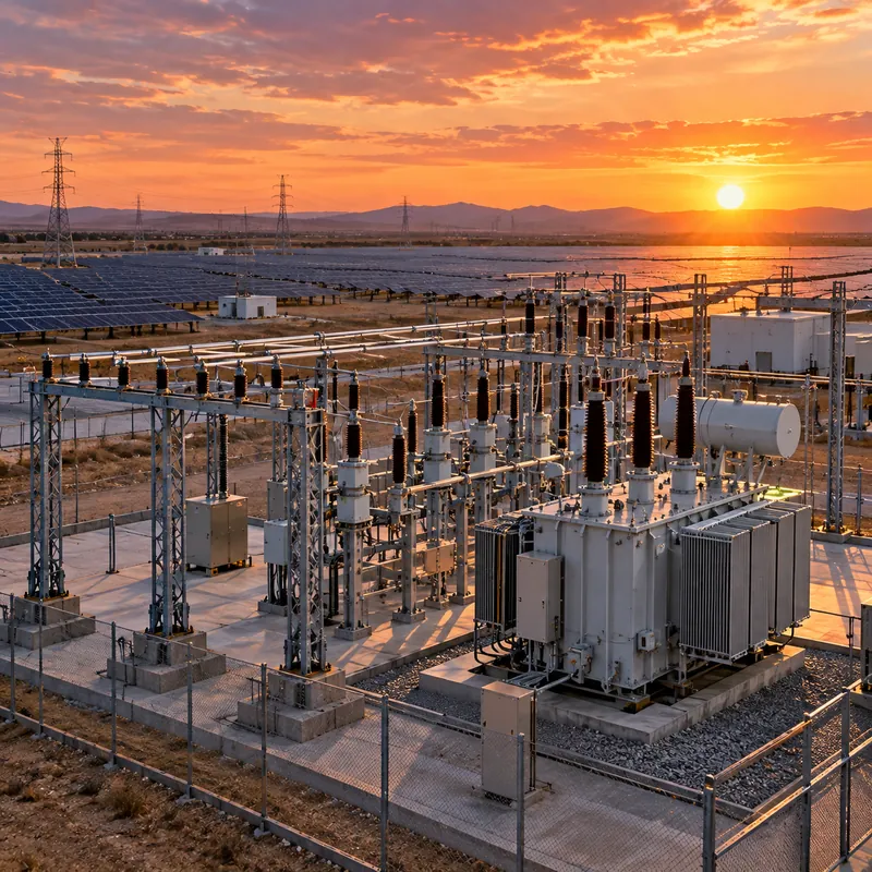
A solar power substation is the step-up and switching station that connects a photovoltaic plant's internal collector network to the utility grid. It is often called the PV collector substation or plant substation, and on the utility's single-line diagram it is the point of interconnection (POI) or sits just behind it.
The electrical chain in a utility-scale plant runs as follows:
- PV strings generate DC at up to 1,000 or 1,500 V.
- Inverters, central or string type, convert to three-phase AC at roughly 0.6–0.8 kV.
- Inverter step-up transformers on MV skids raise voltage to 20–35 kV; see the solar power transformer guide.
- Collector feeders, usually buried cable, loop several skids back to the substation.
- Collector switchgear at the substation protects and switches each feeder.
- Main power transformer (MPT) steps up to transmission or sub-transmission voltage.
- HV breaker, disconnect and metering connect to the utility line or switching station.
Unlike a load-serving substation, power flow is mainly outward and the source is inverter-based, which changes protection behaviour. Inverters deliver limited fault current, typically 1.1–1.5 times rated, so overcurrent elements that work on a utility-fed system may not operate reliably for faults inside the plant.
The general role of substations in any network is introduced in what is a substation.
Solar Substation Architecture by Plant Size
The connection voltage and substation scope scale with plant capacity and with the utility's network at the site.
| Plant AC rating | Typical connection | Substation scope |
|---|---|---|
| Below about 2 MW | LV or 10–20 kV distribution | Inverter transformer, RMU or MV metering cubicle |
| 2–10 MW | 10–35 kV distribution feeder | One or more box-type substations, MV switchboard, utility recloser or metering |
| 10–50 MW | 35–132 kV | Dedicated substation, one MPT up to about 50 MVA, MV collector switchgear |
| 50–300 MW | 110–230 kV | One or two large MPTs, multiple collector buses, HV breaker bays |
| Above 300 MW | 230 kV and above | Multiple MPTs, often a utility switching station and long-term reactive support |
For smaller plants, a compact prefabricated unit combining MV switchgear, transformer and LV board avoids civil works and shortens commissioning; see the box-type substation guide. Above about 10 MW, utilities usually require a dedicated substation with an HV breaker so the plant can be isolated without disturbing other customers.
Battery storage is increasingly added to PV plants, either AC-coupled on the collector bus or DC-coupled at inverter level. AC-coupled storage adds feeders to the collector switchgear and changes MPT loading because charging from the grid reverses power flow; the options are discussed in energy storage systems for solar farm integration.
How Do You Size the Main Power Transformer?
The MPT must carry the plant's real power and the reactive power it is required to exchange at the POI, plus the reactive losses of collector cables and the transformers themselves.
The starting relation is S = √(P² + Q²), or for a power factor requirement, S = P / PF.
- Define the POI requirement: commonly 0.95 leading to 0.95 lagging at rated output, set by the utility or by IEEE 2800-2022 for transmission-connected plants.
- Calculate minimum MVA:
S = P_ac / 0.95. - Add reactive losses: MPT reactive loss is approximately
Q = S × Z%at full load; collector and skid transformers add more. - Check inverter reactive capability can supply this at the POI, or plan capacitor banks or a STATCOM.
- Choose cooling class, for example ONAN/ONAF, so the ONAF rating covers peak output with margin for high ambient.
- Set impedance to limit fault level on the collector bus while keeping voltage regulation acceptable.
- Select tap changer: an on-load tap changer is usually needed to hold POI voltage across grid voltage variation.
Vector group is commonly YNd or YNyn with a delta tertiary. With a delta collector winding, the MV system has no neutral and requires a grounding transformer, covered below.
For load-tap-changer selection and control, see the load tap changer engineering guide.
Worked Example: Substation for a 25 MWac PV Plant
A 25 MWac PV plant connects at 110 kV. The utility requires 0.95 power factor capability at the POI.
Inverter skids: eight 3.15 MVA skids, each with a 0.63/35 kV inverter step-up transformer. LV current per skid: I = 3,150,000 / (1.732 × 630) ≈ 2,887 A, which sets the LV busbar and inverter-to-transformer connection.
Collector feeders: two feeders of four skids, 12.6 MVA each. Current at 35 kV: I = 12,600,000 / (1.732 × 35,000) ≈ 208 A. A 630 A feeder breaker and a cable sized for about 250 A with derating for burial depth and grouping are typical.
MPT rating: S = 25 / 0.95 ≈ 26.3 MVA at the POI. With 10.5% impedance, MPT reactive loss at full load is about 26.3 × 0.105 ≈ 2.8 Mvar, and skid transformers and cables add a few Mvar more. A 110/35 kV transformer rated 25/31.5 MVA ONAN/ONAF with an on-load tap changer covers this with margin.
HV current: I = 31,500,000 / (1.732 × 110,000) ≈ 165 A, well within standard 110 kV breaker ratings; the breaker is selected mainly on fault interrupting duty.
| Item | Selection |
|---|---|
| Main transformer | 25/31.5 MVA, 110/35 kV, YNd11, OLTC, ONAN/ONAF |
| Grounding transformer | 35 kV zigzag (ZNyn) with neutral resistor |
| Collector switchgear | 35 kV, 2 feeder bays, 1 incomer, 1 grounding transformer bay, 1 auxiliary bay |
| Station service | 35/0.4 kV auxiliary transformer |
Grounding and Overvoltage Protection in Solar Substations
A grounding transformer is a transformer, usually zigzag or wye-delta connected, whose purpose is to provide a neutral reference and a path for zero-sequence current on an otherwise ungrounded system. Solar collector systems fed from the delta winding of the MPT need one for two reasons:
- Fault detection: without a ground source, a phase-to-ground fault on a collector cable produces little fault current and can go undetected.
- Temporary overvoltage: if the plant is islanded with a ground fault, unfaulted phases rise toward line-to-line voltage, stressing surge arresters, cable insulation and inverter transformers. Effective grounding limits this rise.
Design of the grounding transformer covers zero-sequence impedance, short-time current rating and the neutral resistor; see the grounding transformer engineering guide.
Substation earthing is designed to IEEE 80 or an equivalent standard so that touch and step voltages during ground faults remain within tolerable limits. PV plants have very large fenced areas and long collector routes, so the substation grid and the array earthing are usually bonded and modelled together.
Surge arresters are installed at the MPT terminals on both sides, at cable-to-overhead transitions and on each skid transformer. Arrester continuous operating voltage must be chosen for the system grounding: a less effectively grounded collector needs higher-rated arresters. Selection is explained in the surge arrester guide.
Lightning shielding of the HV yard follows the rolling sphere or fixed-angle method, with masts or shield wires above outdoor equipment.
Protection, Control and Interconnection Standards
Protection must handle both utility-sourced and inverter-sourced faults. A typical scheme includes:
| Zone | Typical functions (IEEE C37.2 device numbers) |
|---|---|
| Main transformer | 87T differential, 50/51 backup, 63 sudden pressure, 26/49 temperature |
| Collector feeders | 50/51, 50N/51N, 67 directional, 27/59 voltage |
| Collector bus | 87B bus differential on larger plants, 59N neutral overvoltage |
| Point of interconnection | 81O/U frequency, 27/59, 32 directional power where export limits apply, transfer trip from utility |
The power plant controller (PPC) sits above the inverters and regulates active power, ramp rate, voltage or reactive power and frequency response at the POI. It reads revenue metering and the utility's setpoints and dispatches each inverter. Communication commonly uses IEC 61850 or DNP3 to the utility and Modbus TCP to inverters.
Key interconnection standards:
- IEEE 1547-2018 and IEEE 1547.1 for distribution-connected resources
- IEEE 2800-2022 for transmission-connected inverter-based resources
- UL 1741 SB for grid-support inverter listing in the US
- IEEE 519 for harmonic limits at the point of common coupling
- IEC 62271 for switchgear and IEC 60076 for transformers
Protection design principles are covered further in substation protection engineering, and a full drawing set starts with the single line diagram.
Next Steps: Specifying and Sourcing Solar Substation Equipment
A complete RFQ for solar substation equipment should include:
- Plant AC rating, inverter type and skid rating, and number of skids per feeder
- Grid connection voltage, short-circuit level at the POI and the utility's reactive power and voltage requirements
- Preferred vector group, impedance, cooling class and tap changer type for the MPT
- Collector voltage, grounding method and required ground fault current
- Site altitude, ambient temperature range, seismic zone and corrosion class
- Applicable standard: IEC 60076 and IEC 62271, or ANSI/IEEE C57 and C37 variants
MARS manufactures power transformers up to 31,500 kVA and 110 kV class, inverter step-up oil-immersed transformers, compact and containerised transformer substations, KYN28 metal-clad switchgear, SF6 ring main units and grounding and auxiliary transformers. For plants within that rating, MARS can supply the MPT, collector switchgear and skid substations as a coordinated package; larger plants can still use MARS skids and collector equipment. See also the power transformer range.
Every unit receives routine tests and FAT can be witnessed. Send the single-line diagram and grid requirements through the quote request page.
Frequently asked questions
What is a solar substation?
A solar substation is the step-up and switching station that connects a photovoltaic plant to the utility grid. It receives power from the plant's medium-voltage collector feeders, raises it through a main power transformer to grid voltage, and provides protection, metering, grounding and voltage control so the plant meets interconnection requirements.
What voltage do solar farms connect to the grid at?
Small plants below about 2 MW often connect at low voltage or 10 to 20 kV. Plants of roughly 2 to 10 MW commonly connect at 10 to 35 kV distribution feeders. Larger plants connect at 66 to 230 kV through a dedicated substation, and very large plants at 230 kV and above. The utility sets the voltage based on capacity and local network.
How big should a solar plant main transformer be?
Size it for real power plus required reactive capability and losses. Divide plant AC rating by the required power factor, commonly 0.95, then add allowance for transformer and collector reactive losses. A 25 MWac plant needs at least 26.3 MVA, so a 25/31.5 MVA ONAN/ONAF transformer is a typical selection.
Why does a solar farm need a grounding transformer?
When the main transformer's collector winding is delta-connected, the medium-voltage system has no neutral. A grounding transformer creates a neutral path so ground faults produce detectable current, and it limits temporary overvoltage on unfaulted phases if the plant becomes islanded during a fault, protecting arresters, cables and inverter transformers.
What standards apply to solar power substations?
Common standards include IEEE 1547-2018 for distribution interconnection, IEEE 2800-2022 for transmission-connected inverter plants, UL 1741 SB for US inverters, IEEE 519 for harmonics, IEEE 80 for substation grounding, IEC 60076 or IEEE C57.12.00 for transformers, and IEC 62271 or IEEE C37 for switchgear, plus the utility's interconnection handbook.
Can a solar plant use a box-type substation instead of a full substation?
Yes, for plants that connect at distribution voltage, typically below about 10 MW. Box-type substations combine MV switchgear, a step-up transformer and LV switchboard in one prefabricated enclosure. They reduce civil works and site wiring. Larger plants at transmission voltage still need a dedicated substation with HV breakers and protection.
Written and reviewed by the MARS application engineering team in Shanghai, who specify and test transformers, switchgear, substations and battery storage for projects in 40+ countries. Last updated .
Tags: solar power substation solar substation pv collector substation solar main power transformer inverter step-up transformer