Key takeaways
- Modern offshore wind turbines are commonly rated 12 to 15 MW or more, connected in strings by 66 kV array cables to an offshore substation platform.
- An offshore substation steps voltage up to typically 132 to 275 kV HVAC to reduce export current; a 1 GW farm at 220 kV carries roughly 2,800 A in total.
- HVAC export cables generate large charging current, about 2.7 Mvar per km in a 220 kV example, so shunt reactors are installed offshore, onshore or both.
- HVDC export is usually preferred beyond roughly 80 to 150 km of cable, where HVAC reactive power and losses make AC transmission uneconomic.
- Turbine foundations include monopiles, jackets, gravity bases and suction buckets in shallow to medium depths, and floating spar, semi-submersible or tension-leg designs in deep water.
Quick answer: An offshore wind substation is a platform that collects power from a wind farm's 33 kV or 66 kV array cables, steps it up through large power transformers to typically 132–275 kV, and sends it ashore by export cable. It houses gas-insulated switchgear, transformers, reactive compensation, protection and auxiliary systems. Far-from-shore farms use HVDC converter platforms instead.
An offshore wind farm, a wind farm at sea rather than on land, is a power station spread over tens of square kilometres of ocean. Each turbine generates at low voltage, steps up inside its tower, and feeds an array cable network. The offshore substation is where that network converges and where voltage is raised for the long run to shore. Its design drives export cable count, grid compliance and much of the project's availability.
This guide is for engineers, developers and students who want to understand how an offshore wind turbine works electrically, what sits on an offshore substation, how construction and installation proceed, and how onshore wind farm substations compare. It includes a worked sizing example for a 1 GW project.
How Does an Offshore Wind Turbine Work Electrically?
An offshore wind turbine converts wind energy into rotation of a rotor, typically 200–250 m in diameter on current machines, which drives a generator in the nacelle. Most offshore turbines use either a direct-drive permanent magnet generator or a medium-speed geared generator, followed by a full-power back-to-back converter that decouples generator frequency from the 50 or 60 Hz grid.
The electrical path inside the turbine:
- Generator produces variable-frequency AC, commonly at 690 V to a few kV.
- Full converter rectifies and inverts to grid-frequency AC with controllable reactive power.
- Turbine transformer in the nacelle or tower base steps up to the array voltage, now commonly 66 kV.
- Turbine switchgear, usually compact gas-insulated, connects the turbine to incoming and outgoing array cables so a string can loop through.
Turbine transformer design challenges include vibration, limited space, high harmonic content from the converter and marine humidity. These are discussed further in the wind turbine transformer engineering guide, and a broader component overview is in wind turbine electrical components.
The move from 33 kV to 66 kV arrays roughly halved current for the same power, allowing more turbines per string and fewer cable routes into the offshore substation, which matters as turbine ratings rose beyond 10 MW.
What Is an Offshore Substation and What Does It Contain?
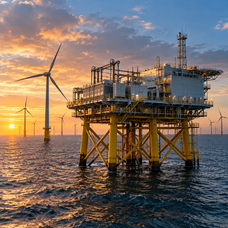
An offshore substation (often called an OSS or offshore transformer module) is a steel topside on a jacket or monopile foundation that receives array cables, transforms voltage and connects the export cables. A typical HVAC offshore wind farm substation contains:
| System | Function | Typical standards |
|---|---|---|
| Array switchgear (33/66 kV GIS) | Terminates and protects each turbine string | IEC 62271-200, IEC 62271-203 |
| Main power transformers | Step up 66 kV to 132–275 kV, often 2 or 3 units for redundancy | IEC 60076 series |
| Export switchgear (HV GIS) | Connects transformers to export cables | IEC 62271-203 |
| Shunt reactors | Compensate cable charging current | IEC 60076-6 |
| Earthing transformers | Provide a neutral and limit earth fault current on the array system | IEC 60076-6 |
| Auxiliary transformers, diesel generator, UPS | Platform power, heating, ventilation, emergency supply | IEC 61892 |
| Protection, control and SCADA | Relays, communications, metering | IEC 61850, IEC 60255 |
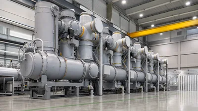
Gas-insulated switchgear dominates because it is compact and sealed from salt air; see gas-insulated switchgear engineering. The array neutral is usually earthed through earthing transformers, as explained in the neutral earthing resistor guide.
Platform design must also meet corrosion protection for offshore exposure (ISO 12944 category CX for coatings), fire and blast segregation of oil-filled transformers, and helicopter or vessel access. Weight and centre of gravity are tightly controlled because the topside is lifted as one piece by a heavy-lift vessel.
HVAC vs HVDC: How Is Offshore Wind Energy Brought Ashore?
Offshore wind energy can be exported by HVAC cables from an AC substation, or by HVDC cables from a converter platform. The choice is driven mainly by distance and capacity.
| Factor | HVAC export | HVDC export |
|---|---|---|
| Typical distance | Up to roughly 80–150 km of cable | Beyond that range, and very large capacities |
| Offshore equipment | Transformers, GIS, reactors | Converter station with valves, transformers, DC switchyard |
| Reactive power | Large cable charging; compensation needed | No steady-state charging current on DC cable |
| Cables per GW | Usually several three-core cables | One bipole pair can carry about 1–2 GW |
| Platform size | Smaller | Much larger and heavier |
| Onshore station | AC substation with reactors, filters, STATCOM as needed | Converter station |
The reason AC distance is limited is cable capacitance. Charging reactive power per phase-set is Q = V² × 2πf × C. For a 220 kV cable with C of about 0.18 µF/km at 50 Hz:
Q = (220,000)² × 314 × 0.18 × 10⁻⁶ ≈ 2.7 Mvar per km
Over 100 km, roughly 270 Mvar of charging must be absorbed by shunt reactors, which also consumes part of the cable's current-carrying capacity. HVDC avoids this and has lower losses over long distances, at the cost of expensive converter platforms.
The grid code of the transmission operator sets reactive power, fault ride-through and harmonic limits at the onshore connection point; see grid integration of renewable energy sources.
Worked Example: Sizing a 1 GW Offshore Wind Farm Substation
A 1 GW HVAC project uses 15 MW turbines, 66 kV arrays and 220 kV export, 60 km from shore.
Turbine count: 1,000 / 15 = 66.7, so 67 turbines (1,005 MW).
Array string current: with five turbines per string at 0.95 power factor:
I = P / (√3 × V × PF) = 75,000,000 / (1.732 × 66,000 × 0.95) ≈ 691 A
This sits within the rating of large-conductor 66 kV array cables at the first section nearest the platform; cable size can step down toward the end of the string. Sixty-seven turbines need about 14 strings, so the 66 kV GIS needs at least 14 feeder bays plus transformer incomers.
Transformer MVA: S = 1,005 / 0.95 ≈ 1,058 MVA. Two transformers of about 530 MVA each give full export with both in service; three of about 360 MVA allow roughly two thirds of output to continue during a transformer outage. The redundancy decision balances capital cost against lost energy.
Export current at 220 kV: I = 1,058,000,000 / (1.732 × 220,000) ≈ 2,777 A. With three export cables, each carries about 925 A, before allowance for charging current.
Reactive compensation: 60 km × 2.7 Mvar/km ≈ 162 Mvar per cable, about 490 Mvar total, typically split between offshore and onshore reactors.
Fault levels, earthing and transient overvoltage studies follow; the method is outlined in our fault current calculation guide.
Offshore Wind Turbine Foundations and Construction
Foundation type is set by water depth, seabed soil, turbine size and installation vessel availability.
- Monopile: a single large steel tube driven or drilled into the seabed, the most common choice in roughly 20–50 m depths; diameters above 10 m are now used for the largest turbines.
- Jacket: a lattice steel structure on three or four piles, used in deeper water and for most offshore substation platforms.
- Gravity-based: a concrete base held by its own weight, suited to hard seabeds where piling is difficult.
- Suction bucket: a steel caisson installed by pumping water out, reducing piling noise.
- Floating: spar, semi-submersible, barge or tension-leg platforms moored to the seabed, used in deep water beyond fixed-bottom limits.
Offshore wind farm construction typically follows this sequence:
- Site survey, geotechnical and unexploded ordnance clearance.
- Foundation installation and scour protection.
- Offshore substation jacket and topside lift.
- Export cable lay and burial, landfall works and onshore substation.
- Array cable lay and pull-in to turbines and platform.
- Turbine tower, nacelle and blade installation by jack-up vessel.
- Energisation, commissioning and reliability runs.
Offshore wind installation is weather-limited, so schedule risk is managed by working windows for wave height and wind speed. Pile driving noise limits apply in many waters, influencing foundation choice. Design standards include IEC 61400-1 for turbines and IEC 61400-3-1 for fixed offshore turbine design requirements.
Wind Farm Substation Onshore: How Does It Compare?
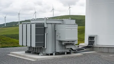
A wind power substation on land performs the same role as an offshore platform but with very different constraints. Onshore wind farms commonly use 33 kV or 35 kV collector circuits and a substation stepping up to 66–220 kV for grid connection. Each turbine often has a pad-mounted or box-type substation at its base instead of a nacelle transformer.
| Aspect | Offshore substation | Onshore wind farm substation |
|---|---|---|
| Collector voltage | 66 kV (older: 33 kV) | 33–35 kV typical |
| Switchgear | GIS, compact and sealed | AIS or GIS; ring main units at turbines |
| Transformer weight limits | Strict, lifted onto topside | Road transport limits only |
| Maintenance access | Vessel or helicopter, weather-dependent | Road access |
| Corrosion class | Offshore marine (CX) | Typically C3–C5 depending on site |
| Auxiliary power | Diesel generator plus UPS on platform | Grid-fed with backup |
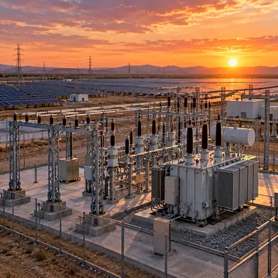
Onshore stations also host grid-forming or reactive power equipment more easily, such as STATCOMs, capacitor banks and battery storage. The same collector-and-step-up architecture appears in large PV plants, covered in the solar substation design guide, and the general construction process is in substation construction.
Next Steps: Specifying and Sourcing Wind Farm Substation Equipment
Offshore export platforms and their multi-hundred-MVA transformers are specialised items built by a small group of heavy-equipment suppliers and fabricators; MARS does not build offshore platform topsides or export transformers in that range. MARS does supply equipment used across onshore wind and the shore side of many projects:
- Oil-immersed and box-type transformer substations for 33–35 kV onshore turbine step-up
- Power transformers up to 31,500 kVA and 110 kV class for smaller onshore wind farm substations
- KYN28 metal-clad switchgear and SF6 ring main units for collector circuits
- Earthing, auxiliary and station service transformers
- LFP containerised BESS from 500 kWh to 10 MWh for firming and grid services
For an RFQ, provide the single-line diagram, collector voltage, turbine rating and count, grid connection voltage, short-circuit level, required vector group, corrosion category, altitude and ambient range, and any grid code reactive power requirement. Units are designed to IEC 60076 and IEC 62271, with GB, ANSI/IEEE and GOST variants.
Submit project details through the quote request page for a technical and commercial proposal.
Frequently asked questions
What does an offshore substation do?
An offshore substation collects power from the wind farm's array cables, typically at 66 kV, and steps it up through power transformers to 132 to 275 kV for export to shore. It also houses switchgear, reactive compensation, protection, control and auxiliary power systems. On very distant farms, an HVDC converter platform performs this role.
How does an offshore wind farm get power to shore?
Turbines feed array cables that run to an offshore substation, which raises voltage and connects to buried subsea export cables. The cables land at a beach or cliff landfall, continue underground to an onshore substation, and connect to the transmission grid. Long-distance projects convert to HVDC offshore and back to AC onshore.
How deep can offshore wind turbines be installed?
Fixed-bottom foundations such as monopiles and jackets are generally used in water up to roughly 50 to 60 metres. Beyond that, floating foundations moored to the seabed, such as spar, semi-submersible or tension-leg platforms, are used. Depth limits depend on soil conditions, turbine size and installation vessel capability.
Why do offshore wind farms use 66 kV array cables?
Raising array voltage from 33 kV to 66 kV halves current for the same power. That allows more large turbines per string, fewer and shorter cable routes, lower losses and fewer switchgear bays on the offshore substation. It became standard as turbine ratings passed about 8 to 10 MW.
When is HVDC used instead of HVAC for offshore wind?
HVDC is usually chosen when export cables exceed roughly 80 to 150 km or when capacity is very large. HVAC cables generate large charging current that must be compensated and that reduces usable capacity over distance. HVDC avoids steady-state charging current and has lower losses on long routes, at the cost of large converter platforms.
What is the difference between an offshore wind farm and an onshore wind farm substation?
Both collect turbine power and step it up for the grid. Offshore substations use compact gas-insulated switchgear, weight-limited transformers, marine corrosion protection and diesel backup on a platform accessed by vessel. Onshore substations usually use 33 to 35 kV collectors, air- or gas-insulated switchgear and have road access for maintenance.
Written and reviewed by the MARS application engineering team in Shanghai, who specify and test transformers, switchgear, substations and battery storage for projects in 40+ countries. Last updated .
Tags: offshore wind substation offshore wind farm offshore substation offshore wind turbine wind farm substation