Key takeaways
- A compliant transformer fire protection system combines passive oil containment, spatial separation or blast fire walls, and active fire suppression systems to limit catastrophic thermal damage.
- NFPA 850 Table 5.1.4.3 mandates a minimum 2-hour fire-rated barrier or spatial separation distances up to 15 metres for mineral-oil-filled units containing over 18,925 litres of fluid.
- High-velocity water spray (HVWS) systems engineered to NFPA 15 require a sustained discharge density between 10.2 and 20.4 L/min/m² over the entire envelope, including conservator tanks and radiators.
- Bushing failures and internal electrical flashovers account for over 70% of catastrophic tank ruptures that ignite mineral oil fires with heat release rates exceeding 30 MW.
- Secondary containment bunds must be sized to retain 100% of the single largest transformer oil volume plus a minimum 10-minute active deluge discharge at maximum operational design flow.
Quick answer: A transformer fire protection system is an integrated network of passive containment barriers, fire separation walls, rapid optical or thermal detection, and active suppression mechanisms—such as high-velocity water deluge, compressed air foam, or inert nitrogen injection—engineered to extinguish mineral oil fires, prevent tank rupture escalation, and isolate adjacent grid infrastructure.
High-voltage power transformers represent some of the most critical and capital-intensive assets across transmission and distribution networks. Because large units can contain tens of thousands of litres of combustible hydrocarbon-based mineral insulating oil operating under elevated electrical and thermal stresses, an internal fault can quickly transition into a devastating deflagration. Understanding the design, hydraulic requirements, and civil integration of an active and passive fire mitigation system is essential for substation reliability and life safety.
Transformer Fire Risks and Failure Mechanisms
Transformer fires originate primarily from sudden electrical insulation breakdown, internal arcing, high-energy partial discharges, or severe mechanical failure within major sub-components. According to industry reliability statistics, transformer bushings and on-load tap changers are the two most common mechanical failure points triggering tank breaches. When a high-energy phase-to-earth fault occurs under oil, the intense arc vaporises the dielectric fluid almost instantaneously, generating an explosive mix of hydrogen, acetylene, and low-molecular-weight hydrocarbons.
This gas generation creates an acoustic dynamic pressure wave that propagates outward at approximately 1,200 metres per second. If the internal mechanical stress exceeds the elastic yield limits of the welded steel tank before mechanical relief devices—such as spring-loaded pressure relief valves (PRVs) or rapid rise relays—can vent the volume, the tank tears open. The combustible gases and atomised oil erupt into the ambient atmosphere, mixing with oxygen and igniting upon contact with the electrical arc. Uncontrolled, these mineral oil fires burn at temperatures exceeding 1,000°C with heat release rates (HRR) often surpassing 30 to 50 megawatts, easily threatening nearby control rooms, busbars, and companion transformers.
Passive Transformer Fire Protection: Fire Walls and Separation
Passive transformer fire protection provides structural defence against radiant heat exposure and projectile fragmentation without requiring mechanical initiation or external control signals. Siting standards such as NFPA 850 and IEEE 979 stipulate clear spatial separation distances between adjacent oil-insulated electrical equipment based on the total volume of liquid fuel.
When site constraints or compact substation topologies prevent achieving clear horizontal separation distances—often up to 15 metres for transformers holding more than 18,925 litres (5,000 US gallons) of mineral oil—a dedicated transformer fire wall must be installed. These blast-resistant fire barriers typically consist of reinforced concrete, structural steel with intumescent coatings, or pre-cast concrete panels rated for a minimum fire resistance period of 2 to 4 hours under ISO 834 or UL 1709 high-heat hydrocarbon burn curves.
The physical footprint of a protective wall must extend beyond the thermal envelope of the transformer. To provide effective shielding against line-of-sight thermal radiation, the barrier must extend at least 0.3 to 0.6 metres above the highest oil-filled component—normally the high-voltage bushings or the oil conservator tank—and 0.6 metres beyond the lateral extremities of the tank radiators.
Oil Containment and Drainage Pit Engineering
Secondary oil containment systems capture burning dielectric fluid and prevent hazardous environmental release into local drainage channels or groundwater tables. Under IEEE 980 and IEC 61936-1 clause 8.7, a complete containment assembly comprises an under-tank catchment basin, a flame-quenching crushed rock layer, and an external holding retention sump or oil-water separator.
The structural gravel bed directly below the transformer must be filled with washed, round stone (typically 20 mm to 40 mm aggregate diameter) to a minimum depth of 300 mm. This layer acts as a mechanical flame trap: as burning mineral oil spills through the stone voids, the high surface area of the cold rock rapidly cools the fluid below its fire point (typically 140°C to 170°C for standard mineral oil), extinguishing liquid-phase surface combustion before it can pool and burn violently.
The hydraulic capacity of the retention system must be sized according to strict engineering criteria:
- Calculate the total liquid volume of dielectric fluid contained within the transformer tank, coolers, and conservator.
- Calculate the total water discharge volume generated by the active fire suppression system operating continuously for its specified design run time (typically a minimum of 10 minutes at rated hydraulic capacity).
- Add a safety allowance for the maximum anticipated 24-hour rainfall event for the local geographical region.
For facilities utilising natural or forced oil cooling designs, reference our detailed review of ONAF transformer cooling systems to evaluate fluid migration characteristics across external radiator banks.
Active Transformer Fire Suppression System Technologies
An active transformer fire suppression system discharges a dedicated extinguishing agent directly onto the hazard zone following electrical or thermal detection. Depending on equipment location, ambient environmental conditions, water supply infrastructure, and transformer construction, substation engineers deploy three primary active systems.
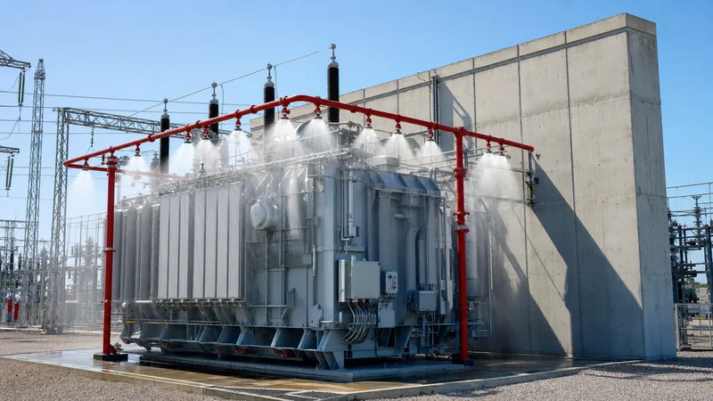
The most widely utilised method for outdoor distribution and transmission substations is the high-velocity water spray (HVWS) deluge system. Operating under NFPA 15, directional nozzles atomise water into dense droplets that cool the metal tank skin below the oil flash point, displace oxygen at the liquid interface through rapid steam generation, and emulsify surface oil to form a non-flammable water-in-oil film.
In locations where water supplies are restricted or freezing temperatures present operational challenges, Compressed Air Foam (CAF) systems offer lower water volumetric requirements while providing an insulating blanket that suffocates hydrocarbon vapour generation. Alternatively, Nitrogen Injection Fire Protection Systems (NIFPS) act directly inside the transformer tank. Upon simultaneous signal confirmation from mechanical trip relays and tank thermal sensors, a rupture disc opens, draining a small volume of oil to create headspace while injecting high-pressure nitrogen gas into the bottom of the tank. The bubbling inert nitrogen rapidly stirs the liquid, bringing colder bottom oil to the surface to drop the temperature below its fire point while displacing combustible internal gases.
Comprehensive asset oversight also relies on early detection systems, which can be explored in our guide to transformer monitoring systems.
Water Spray Deluge Sizing: Worked Hydraulic Calculation
Designing an effective high-velocity water deluge system requires precise calculation of water supply volume and pump head pressure to satisfy the statutory discharge density across every exposed transformer surface. Under NFPA 15 clause 7.4.1, high-velocity water spray systems safeguarding oil-immersed transformers require a minimum continuous design density of 10.2 litres per minute per square metre (0.25 gpm/ft²) across the rectangular prism envelope of the main tank, radiators, and conservator.
Consider a 110 kV, 40 MVA oil-immersed power transformer with the following conservative envelope dimensions:
- Main tank: Length = 6.0 m, Width = 3.2 m, Height = 4.0 m
- Radiator bank envelope (2 banks): Total projection Length = 4.0 m, Width = 1.8 m, Height = 3.5 m each
- Conservator tank: Diameter = 1.2 m, Length = 4.5 m (projected envelope)
Step 1: Calculate total enveloped surface area ($A_{total}$):
- Main tank (four vertical sides + top): $(2 \times [6.0 \times 4.0]) + (2 \times [3.2 \times 4.0]) + (6.0 \times 3.2) = 48.0 + 25.6 + 19.2 = 92.8\text{ m}^2$
- Radiator banks (two separate banks, exterior exposed faces): $2 \times [(2 \times [4.0 \times 3.5]) + (2 \times [1.8 \times 3.5]) + (4.0 \times 1.8)] = 2 \times [28.0 + 12.6 + 7.2] = 95.6\text{ m}^2$
- Conservator tank and piping allowance: $\approx 22.0\text{ m}^2$
- Total protected surface area: $A_{total} = 92.8 + 95.6 + 22.0 = 210.4\text{ m}^2$
Step 2: Determine required net discharge flow ($Q_{design}$):
$$Q_{design} = A_{total} \times \text{Design Density} = 210.4\text{ m}^2 \times 10.2\text{ L/min/m}^2 = 2,146.1\text{ L/min}$$
Step 3: Include hydraulic system imbalance and piping overspill factor (typically 15% to 20% allowance for hydraulic elevation and nozzle friction variations):
$$Q_{system} = 2,146.1\text{ L/min} \times 1.20 = 2,575.3\text{ L/min} \approx 154.5\text{ m}^3/\text{hr}$$
Step 4: Calculate total water storage requirement for a standard 30-minute operational duration:
$$\text{Total Water Storage} = 2,575.3\text{ L/min} \times 30\text{ min} = 77,259\text{ litres} \approx 77.3\text{ m}^3$$
This required water volume must be held in an adjacent firewater storage tank equipped with redundant diesel-driven or emergency-backed electric fire pumps capable of maintaining a residual nozzle pressure of at least 3.5 bar (350 kPa) at the hydraulically most remote spray head.
Standards and Design Comparison for Fire Mitigation
Substation fire protection involves multiple regulatory standards governing electrical safety, structural fire ratings, and hydraulic delivery parameters. The following matrix compares the performance benchmarks across primary international specifications.
| Standard | Scope & Focus | Passive Separation Requirements | Active System Design Densities | Drainage & Environmental Mandates |
|---|---|---|---|---|
| NFPA 850 | Electric generating plants and HVDC/AC converter stations | Spatial clearance: 7.6 m to 15 m based on oil volume; or 2-hour rated fire wall | Deluge densities per NFPA 15: 10.2 L/min/m² over tank envelope | Retention pit must hold 100% oil volume + 10-minute fire suppression water |
| IEEE 979 | Substation fire protection guide | Separation based on fire hazard severity classification (clearances up to 15.2 m) | Water deluge, nitrogen injection, foam, or water mist depending on risk profile | Recommends stone-filled collection pits discharging to an oil separator |
| IEC 61936-1 | Power installations exceeding 1 kV AC | Minimum clearances (cl. 8.7.2): 3 m to 5 m for <1,000 L; 5 m to 10 m for >1,000 L; or REI 60/90 fire wall | Recommends automatic fixed extinguishing installations for indoor units or critical grids | Crushed aggregate pit (300 mm deep, 40 mm gravel) or retention tank sized to 100% fluid |
| FM Global DS 5-4 | Property loss prevention data sheets | 3-hour fire-rated barrier wall if distance is less than 9 m to 15 m from building/transformer | 10.2 L/min/m² for main surfaces; 14.3 L/min/m² for high-voltage bushings | Drainage capacity designed for fluid discharge without pool pooling near equipment |
To reduce internal arcing risks that initiate these high-energy fires, electrical teams must also review proper protective relay configurations as outlined in our overview of transformer protection systems.
Pre-Commissioning and Site Acceptance Inspection Checklist
A thorough verification protocol ensures that all physical containment systems, blast shielding, and active suppression systems operate harmoniously prior to energisation. Engineering procurement and construction (EPC) contractors should execute this field checklist during site acceptance testing (SAT).
- Passive Containment and Drainage Verification: Inspect the under-tank collection pit to confirm clear gravel depth (minimum 300 mm) with round, uncrushed, washed stone (20 mm to 40 mm). Confirm drainage outlet grates are unobstructed and sump diversion valves actuate freely to the oil-water separator.
- Transformer Fire Wall Structural Audit: Verify fire-rated boundary panels meet project acoustic and thermal specifications (REI 120 or REI 240 certified). Confirm structural expansion joints use intumescent mastic and that no metal conduits bridge the barrier without fire-stopping seals.
- Hydraulic Pipework and Nozzle Alignment: Check that all high-velocity spray nozzles point toward target surfaces (bushings, cable boxes, main tank, conservator) with zero line-of-sight obstruction from cable trays. Verify pipework supports accommodate mechanical reaction forces generated during rapid deluge valve opening.
- Deluge Valve Trip and Flow Testing: Perform a full wet-trip test. Measure residual hydraulic pressure at the most remote hydraulic nozzle using a calibrated test gauge to ensure dynamic pressure meets or exceeds the minimum 3.5 bar requirement.
- Electrical and Trip Integration: Confirm electrical interlocks between linear heat detection cables, optical flame scanners, transformer differential protection trips, and the master fire alarm control panel (FACP). Verify that deluge initiation automatically triggers alarm annunciation at the supervisory control and data acquisition (SCADA) interface.
- Bushings and Ancillary Health: Inspect high-voltage terminal assemblies for structural damage or micro-cracks before pressurising extinguishing headers; review our technical guide on transformer bushings for mechanical integrity baselines.
Next Steps: Specifying and Sourcing
Sourcing an integrated electrical plant that balances high reliability with code-compliant fire safety requires detailed technical coordination. When preparing your request for quotation (RFQ), ensure you furnish our engineering department with your site plan drawings, ambient climatic profiles, dielectric liquid type (mineral oil vs synthetic ester), single-line diagrams, and substation clear separation boundaries.
We build robust, type-tested equipment designed to integrate with automated deluge, foam, and fire wall installations across complex utilities. Review our high-voltage power transformers, explore complete turnkey assemblies in our prefabricated transformer substations, or browse our standard oil-immersed distribution transformers. To submit your mechanical and electrical datasheets for factory review, contact our technical sales team directly via our contact page or request a formal project proposal through our quote page.
Frequently asked questions
What is the primary function of a transformer fire protection system?
A transformer fire protection system prevents structural tank failure, extinguishes active liquid mineral oil fires, and protects adjacent electrical apparatus from radiant thermal damage. It combines passive fire walls and gravel containment with active suppression like water spray deluge or nitrogen injection.
When is a transformer fire wall required in a substation?
A transformer fire wall is required whenever the physical clearance distance between adjacent transformers, or between a transformer and a building, is less than the minimum safety clearances mandated by NFPA 850 or IEC 61936-1. These separation distances typically range from 7.6 to 15 metres depending on oil volume.
How does crushed gravel in a transformer pit quench oil fires?
Crushed gravel quenches oil fires by rapidly conducting thermal energy away from burning dielectric oil as it flows between the aggregate voids. By cooling the oil below its fire point and starving the pool of oxygen, the stone bed extinguishes burning liquid before it pools.
What water flow rate is required for transformer deluge systems?
NFPA 15 mandates a minimum design density between 10.2 and 20.4 litres per minute per square metre over the projected surface envelope of the transformer. Systems must sustain this hydraulic density continuously for at least 30 to 60 minutes with a minimum nozzle pressure of 3.5 bar.
Can synthetic ester fluids replace active fire protection systems?
Synthetic and natural ester fluids significantly lower fire risk due to their high fire point exceeding 300°C (K-class liquids), which often allows reduced spatial clearances or smaller fire walls under NFPA 850. However, secondary bund containment and early fault detection systems remain mandatory.
Tags: transformer fire protection system transformer fire protection transformer fire wall transformer fire suppression system


