Key takeaways
- Underground mining electrical equipment requires flameproof (Ex d) or explosion-proof enclosures rated to IEC 60079-1 or MSHA 30 CFR Part 75 to operate safely in hazardous methane and coal-dust environments.
- Power distribution in mines relies on resistance-grounded neutral systems limiting phase-to-ground fault current to between 0.5 A and 15 A to prevent lethal touch potentials and explosive arc ignition.
- Underground mobile load centres and power centres step down primary reticulation voltages (typically 6.6 kV, 11 kV, or 13.8 kV) to working machine voltages such as 1,000 V or 415 V using ventilated dry-type cast resin transformers.
- Continuous ground-wire monitoring and pilot wire check circuits are mandatory under IEEE 242 and AS/NZS 4871 to instantly trip circuit breakers within 100 milliseconds if an earth conductor fails.
- Trailing cables supplying mobile production machinery must comply with heavy-duty mining standards such as AS/NZS 2802 or ICEA S-75-381, featuring individual phase screening and semi-conductive elastomer bedding.
Quick answer: Underground mining electrical equipment comprises flameproof medium-voltage switchgear, explosion-proof power centres, mobile dry-type substations, gate end boxes, and trailing cable systems designed to distribute electrical power safely in confined, combustible, and mechanically harsh subterranean environments. These systems utilise high-resistance neutral earthing, continuous ground-wire monitoring, and ruggedised enclosures conforming to IEC 60079, MSHA 30 CFR, and AS/NZS 4871 standards.
Subterranean extractive operations present some of the most unforgiving electrical operating conditions in modern industry. Engineers must overcome extreme ambient humidity, acidic mine drainage, pervasive rock dust, restricted mechanical clearances, and the ever-present threat of explosive atmospheres caused by firedamp (methane) and suspended coal dust. Providing reliable underground mining electrical equipment demands specialized mechanical construction, uncompromising dielectric insulation systems, and sensitive protection schemes capable of clearing faults in fractions of a cycle before an ignition event can propagate.
Surface grid power must be transferred thousands of metres underground via vertical boreholes or drift slopes, stepped down through cascaded switchboards, and delivered directly to high-capacity extraction machines such as continuous miners, longwall shearers, jumbo drills, and haulage conveyors. Mastering the fundamentals of electrical power distribution in mines ensures operational continuity while shielding mining personnel from severe arc-flash hazards, step-and-touch potentials, and toxic atmospheric combustions.
Architecture of Electrical Power Distribution in Mines
Electrical power distribution in mines originates at a primary surface substation, typically receiving utility supply at 33 kV, 66 kV, or 132 kV, which steps down the voltage to an underground distribution level between 6.6 kV and 22 kV.
The primary incoming supply feeds an array of surface-mounted MV switchgear configured in a ring main or dual-radial feeder topology. From this surface switchyard, armoured feeder cables descend into the underground workings through vertical borehole sleeves encased in concrete or via declined conveyor drifts. Borehole cables are suspended under high mechanical tension using engineered borehole cleats designed to support the deadweight of steel-wire armoured (SWA) or copper-tape screened ethylene propylene rubber (EPR) insulated cables spanning vertical depths exceeding 500 metres.
Once at the pit bottom or main distribution level, the high-voltage feeders terminate into a central underground switching station. This station acts as the primary reticulation hub, distributing power across the extraction districts. A typical mining power distribution network divides into three distinct hierarchical tiers:
- Primary Subterranean Reticulation (6.6 kV to 22 kV): High-voltage ring or loop feeds distributing bulk power along permanent haulage roadways to district load centres. Incorporates fully segregated metal-clad switchgear with integrated earth switches and vacuum interrupting devices.
- Secondary Section Reticulation (1 kV to 3.3 kV): Transportable power centres situated 100 to 300 metres behind the active mining face step down voltage to supply medium-power continuous haulage systems, ventilation fans, and secondary booster pumps.
- Face Distribution (400 V to 1,140 V): Flameproof section distribution centres and gate end boxes (GEBs) providing multi-circuit branch control and motor management for front-line extraction equipment operating in hazardous Zone 1 / Group I environments.
Because underground roadways progress continuously as ore or coal is extracted, this reticulation infrastructure must balance structural permanence with modular portability. System designers incorporate modular, transportable skids rather than permanent civil switchrooms to ensure infrastructure relocations occur with minimal operational downtime.
Underground Mining Electrical Equipment: Core Apparatus & Classifications
Underground mining electrical equipment is classified according to the hazardous area environment in which it operates, defined primarily by Group I (coal mining with methane risk) and Group II (metalliferous mining without explosive gases) under IEC 60079-0.
In gaseous coal mines, all electrical equipment used in mines situated within return airways, working faces, or within specified distances of active extraction must carry flameproof (Ex d), increased safety (Ex e), or intrinsic safety (Ex i) certification. A flameproof enclosure is engineered to withstand an internal explosion of an accumulated gas mixture without allowing the resulting flame front or hot gases to ignite the surrounding external atmosphere across machined flame paths.
The primary classes of electrical equipment used in mines encompass the following assemblies:
- Underground Power Centres (Minisubstations): Heavy-gauge steel skid-mounted units housing a primary vacuum circuit breaker or load-break switch, a high-efficiency dry-type transformer, and multi-circuit low-voltage outgoing switchboards protected by individual circuit breakers.
- Gate End Boxes (GEB): Compact, explosion-proof modular control enclosures placed at the entrance to an extraction panel, integrating vacuum contactors, microprocessor motor protection relays, and pilot-circuit monitors to manage individual machines.
- Explosion-Proof Section Isolators: Heavy-duty load-break disconnect switches providing visible positive isolation and earthing facilities for maintenance lockout procedures along distribution roadways.
- Intrinsically Safe (IS) Instrumentation: Sensor networks, environmental methane detectors, emergency stop pull-wires, and programmable logic controller (PLC) remote I/O nodes operating below energy thresholds (typically under 1.5 mJ and 30 V) incapable of releasing an ignition spark.
For hard-rock (metalliferous) mines extracting gold, copper, or nickel, flammable firedamp atmospheres are rarely present, allowing the use of ruggedised industrial enclosures with IP66 ingress ratings and high arc-resistant classifications rather than heavy cast or fabricated flameproof vessels.
Flameproof and Explosion-Protected Switchgear Specifications
Flameproof switchgear in subterranean coal operations must comply with rigorous mechanical and thermal parameters defined by IEC 60079-1 and regional standards such as AS/NZS 4871.1 and MSHA 30 CFR Part 75.
The primary design principle of Ex d equipment relies on the "flame path"—a precision-machined gap between structural mating flanges. When an internal arc flashes over and detonates trapped methane (CH4) gas, internal pressures can spike up to 800 kPa to 1,000 kPa (8 to 10 bar). The enclosure walls must withstand this internal deflagration without rupture or permanent plastic deformation. Simultaneously, the escaping gas must travel through the narrow flame path, where the thermal mass of the heavy steel flanges cools the gas below the auto-ignition temperature of methane (approximately 537 °C) before it reaches the mine atmosphere.
Key structural and electrical requirements for Group I flameproof enclosures include:
- Wall Construction: Fabricated boiler-plate carbon steel or structural stainless steel with wall thicknesses rarely less than 12 mm to 20 mm, reinforced with internal stiffeners to prevent shell deflection under explosive shock waves.
- Flame Path Tolerances: Maximum permitted flame path gap widths typically range from 0.4 mm down to 0.15 mm, with a minimum engagement path length of 12.5 mm to 25 mm, depending on internal volume in accordance with IEC 60079-1 Table 1.
- Mechanical Fasteners: High-tensile socket-head cap screws (minimum Grade 8.8 or Grade 10.9) counterbored into protective shrouds to prevent unauthorised removal or mechanical shearing caused by moving mine rolling stock.
- Interlocking Mechanisms: Mechanical and electrical fail-safe interlocks preventing the opening of the main access door while the internal vacuum switch is energised, and preventing switch closure while the enclosure is open.
Modern subterranean switchboards increasingly utilise vacuum circuit breakers inside flameproof housings because vacuum bottles generate zero hot ionised exhaust gases during fault interruption, significantly reducing internal pressurisation risks compared to older air-break or oil-break alternatives.
Mobile and Skid-Mounted Power Distribution in Mines
Skid-mounted mobile substations provide the critical electrical transformation and section protection required to keep pace with rapid face advances in modern room-and-pillar and longwall operations.
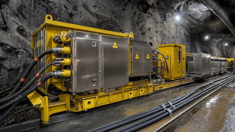
A typical underground mining power centre integrates three distinct compartments onto a rigid structural steel chassis equipped with towing eyes, lifting lugs, and replaceable heavy-duty wear runners. To withstand continuous dragging across jagged, unpaved bedrock, the base frame is designed to endure torsional flexing without transmitting bending stress to internal electrical components or transformer core laminations. For large systems with high tractive requirements, engineers specify features similar to those found in surface mobile substations, such as integrated hydraulic tramming or integrated wheel sets adapted for subterranean rail systems.
The incoming medium-voltage compartment contains an incoming cable coupler receptacle (typically rated 6.6 kV to 11 kV, 200 A to 400 A), a three-position disconnect switch (Closed-Open-Earthed), and capacitive voltage presence indicators. The transformation compartment contains an air-cooled, dry-type transformer with Class H or Class 220 insulation. Liquid-immersed transformers using mineral oil are strictly prohibited in underground coal extraction due to fire and toxic smoke hazards under standards such as NFPA 122.
The low-voltage outgoing section comprises multiple circuit feeds operating at 400 V, 1,000 V, or 3,300 V. Each feeder is managed by an independent vacuum contactor or moulded-case circuit breaker (MCCB) paired with comprehensive electronic protection monitoring:
- Microprocessor-based overcurrent and short-circuit protection with inverse definite minimum time (IDMT) curves.
- Zero-sequence ground-fault detection sensitive down to milliamperes.
- Pilot-wire continuity check and earth-continuity loop monitoring.
- Frozen contact detection and incoming supply phase-sequence monitoring.
- Local and remote industrial Ethernet or serial communications over mining-grade fibre optic links.
Ground Fault Protection, Neutral Grounding, and Pilot Monitoring
Neutral grounding and earth fault protection schemes in mining power distribution are engineered primarily to mitigate electric shock hazards to machine operators standing directly on damp, conductive mine floors.
Ungrounded (floating) distribution systems are unsafe for underground coal mining due to high overvoltages caused by arcing grounds and the difficulty of locating initial insulation breakdowns. Conversely, solidly grounded systems generate devastating phase-to-ground fault currents that instantly vaporise metal, ignite coal dust, and generate dangerous touch potentials across machine chassis. Consequently, global mining standards (including AS/NZS 4871, IEEE 242 Clause 8.4, and MSHA regulations) mandate the implementation of Resistance Grounded Neutral (RGN) systems, often referred to as Neutral Grounding Resistor (NGR) systems.
In a typical 1,000 V face distribution network, the star point of the supply transformer is tied to earth through a metallic alloy NGR sized to restrict the maximum theoretical prospective phase-to-ground fault current. Common industry limits restrict this current to:
- Coal Face Working (1,000 V): Maximum ground-fault current restricted to 0.5 A or 1.0 A.
- Hard-Rock Distribution (6.6 kV / 11 kV): Maximum ground-fault current restricted to 5.0 A or 10.0 A.
- Main Substation Primary Feeders: Maximum ground-fault current limited to 15.0 A or 25.0 A.
By restricting the maximum ground-fault current to 1.0 A on a 1,000 V network, the touch voltage appearing on the frame of an excavator or shuttle car during an insulation breakdown is maintained well below the recognised physiological fibrillation threshold (typically 25 V to 50 V RMS under IEEE 80 / AS 4871). The zero-sequence current transformer (ZSCT) detects these small leakage currents and activates the protective trip relay within 20 to 100 milliseconds.
Continuous earth-conductor integrity is secured through Pilot Wire Monitoring circuits. A low-voltage, intrinsically safe sensing signal runs along an auxiliary pilot core inside the flexible trailing cable to the machine frame and returns via the main earth conductors. If the earth conductor suffers mechanical stretching, partial fracture, or open-circuit failure, the pilot loop impedance shifts, causing the main supply breaker inside the gate end box to open instantly, preventing the machine chassis from becoming a live conductor.
Engineering Comparison: Electrical Equipment Used in Mines
Selecting electrical equipment used in mines requires a careful comparative assessment of technical specifications across coal, metalliferous, and general surface processing applications.
The following engineering comparison table contrasts the operational parameters, enclosure specifications, earthing requirements, and applicable standards for core power apparatus across different mining environments:
| Apparatus Category | Operating Voltage (kV) | Enclosure Protection Rating | Earthing / Neutral Grounding Method | Applicable Safety Standards | Primary Application Context |
|---|---|---|---|---|---|
| Underground Flameproof Gate End Box | 0.400 - 1.140 kV | Ex d [I] Mb, IP66, 10 bar internal deflagration rated | Resistance grounded (current ≤ 1.0 A) with pilot check loop | IEC 60079-1, AS/NZS 4871.4, MSHA 30 CFR 75 | Direct motor control of continuous miners, face conveyors, and drills in gaseous coal seams |
| Underground Mobile Power Centre | 3.3 - 11.0 kV primary / 0.4 - 1.14 kV secondary | Ex d or heavy industrial ingress-protected steel housing on drag skid | Transformer neutral derived via zigzag grounding transformer + NGR (≤ 5.0 A) | IEC 60076-11, IEEE C57.12.01, AS/NZS 4871.2 | Substation transformation situated 150 m from working face |
| Hard-Rock Section Load Centre | 6.6 - 13.8 kV primary / 0.415 - 1.0 kV secondary | Heavy-duty sheet steel, IP56 / NEMA 4X, non-explosion proof | Resistance grounded (≤ 10.0 A) or low-resistance grounded | IEC 62271-200, CSA M421, IEEE C37.20.2 | Non-gaseous metalliferous extraction headings and decline ramps |
| Subterranean HV Switchboard | 6.6 - 22.0 kV | Metal-clad, internal arc classified (IAC AFLR ≥ 25 kA / 1 s) | High-resistance or low-resistance grounding with sensitive ZSCTs | IEC 62271-200, IEEE C37.20.2, AS 62271.200 | Main pit-bottom and district junction distribution substations |
| High-Voltage Cable Coupler Assemblies | 3.3 - 15.0 kV | Ex d or heavy cast aluminum / bronze alloy, IP67 | Phase-segregated copper-screened earth paths with dual pilot pins | AS/NZS 1300, MSHA 30 CFR 77, IEC 60079-0 | Quick-release coupling for extension and relocation of mining trailing cables |
Incorporating arc-resistant construction tested to IEC 62271-200 Appendix A remains essential across both coal and hard-rock infrastructure. Mitigating catastrophic blast damage through rapid venting channels protects personnel working in confined underground cross-cuts, as detailed in our guide on arc-flash safety.
Worked Engineering Calculation: Touch Potential and NGR Sizing
Sizing the neutral grounding resistor (NGR) and determining prospective touch potential is a primary calculation required when designing electrical power distribution in mines.
Consider a 1,000 V continuous miner section fed from an underground power centre via a 200-metre trailing cable. The system parameters are defined as follows:
- System Line-to-Line Voltage ($V_{LL}$): $1,000\text{ V}$ (Phase-to-Neutral Voltage $V_{LN} = 1,000 / \sqrt{3} = 577.35\text{ V}$)
- Target Maximum Ground-Fault Current ($I_{F}$): $1.0\text{ A}$
- Trailing Cable Length ($L$): $200\text{ m}$
- Trailing Cable Protective Earth (PE) Conductor Resistance ($R_{PE}$): $0.45\ \Omega / \text{km}$ total equivalent loop (accounting for two paralleled earth cores)
- Ground Grid & Bond Resistance at Load Centre ($R_{grid}$): $0.5\ \Omega$
Step 1: Calculate the Required NGR Resistance ($R_{NGR}$)
To restrict the maximum phase-to-ground current to exactly $1.0\text{ A}$ during a bolted zero-impedance phase-to-frame fault, the resistor value must dominate the circuit impedance:
$$R_{NGR} = \frac{V_{LN}}{I_{F}} = \frac{577.35\text{ V}}{1.0\text{ A}} = 577.35\ \Omega$$
Engineers specify a continuous or 10-second rated non-inductive alloy resistor rated at $577\ \Omega$, with a continuous thermal dissipation capacity equal to:
$$P = (I_{F})^2 \times R_{NGR} = (1.0\text{ A})^2 \times 577.35\ \Omega = 577.35\text{ W}$$
A 1.0 kW to 1.5 kW continuous power rating is specified to provide thermal margin during extended ground-fault alarm conditions.
Step 2: Calculate Machine Frame Resistance to Earth ($R_{return}$)
The resistance of the trailing cable ground path back to the power centre is:
$$R_{cable\_PE} = 0.2\text{ km} \times 0.45\ \Omega/\text{km} = 0.09\ \Omega$$
Total return path resistance including substation ground:
$$R_{return} = R_{cable\_PE} + R_{grid} = 0.09\ \Omega + 0.5\ \Omega = 0.59\ \Omega$$
Step 3: Determine Maximum Prospective Touch Potential ($V_{touch}$)
When an insulation fault occurs, the touch potential appearing on the external body of the continuous miner relative to true ground is governed by the product of the fault current and the return path resistance:
$$V_{touch} = I_{F} \times R_{return} = 1.0\text{ A} \times 0.59\ \Omega = 0.59\text{ V}$$
Even if the load-centre ground grid degrades to $10.0\ \Omega$, the maximum touch voltage remains:
$$V_{touch\_degraded} = 1.0\text{ A} \times (0.09\ \Omega + 10.0\ \Omega) = 10.09\text{ V}$$
This is well below the statutory 25 V AC threshold established by AS/NZS 4871.1 and MSHA guidelines, preventing lethal ventricular fibrillation and ensuring electrical safety for operating miners.
Cable Management, Couplers, and Trailing Cable Safety in Mining Power Distribution
Flexible trailing cables and reelable cables represent the most vulnerable link in the subterranean mining power distribution chain, enduring severe mechanical tension, crushing from mobile haulage units, and continuous abrasion.
Mining-grade cables are manufactured with heavy elastomer sheaths, typically ethylene propylene rubber (EPR) insulation with an outer jacket of chlorosulphonated polyethylene (CSPE), chlorinated polyethylene (CPE), or heavy-duty polyurethane. Modern designs adhere to international specifications such as AS/NZS 2802, ICEA S-75-381 / NEMA WC 58, and BS 6708. Trailing cables contain three power conductors, one or two earth conductors, and an insulated pilot monitoring conductor positioned symmetrically in the cable interstices to prevent physical crushing between main conductors.
Electrical phase screening is a mandatory protective feature. Each insulated phase core is completely wrapped in a composite tinned-copper wire and polyester yarn braid or a semi-conductive elastomer layer. This design guarantees that any physical piercing by a continuous miner pick or drill steel immediately makes contact with the grounded screen before penetrating the live copper phase, tripping the sensitive earth-leakage relay in milliseconds before phase-to-phase short-circuit energy can spark a fatal fire or flashover.
Cables are coupled together using specialised medium-voltage connectors known as mine cable couplers (rated from 3.3 kV to 15 kV, up to 500 A). These couplers feature heavy cast aluminum or bronze housings with phase-segregated silicone rubber insulators. Mechanical pin configurations enforce a "first-make, last-break" ground connection: when the coupler is disengaged, the pilot pin disconnects first, immediately de-energising the circuit breaker at the gate end box before the main power contacts separate, eliminating arc flash exposure to personnel.
Factory Testing, Inspection Checklist, and Commissioning Protocol
Pre-commissioning and routine statutory testing of underground mining electrical equipment verify that mechanical flame paths, earthing loops, and dielectric barriers remain fully functional prior to subterranean energisation.
Commissioning engineers and procurement inspectors should verify the following points using this structured technical inspection checklist before equipment deployment:
- Flamepath Verification (Ex d units): Measure flange gaps with precision feeler gauges along the full perimeter of all flameproof joints. Confirm gap width is within statutory limits (e.g., ≤ 0.4 mm for gap lengths ≥ 25 mm). Check for scoring, surface corrosion, pitting, or presence of non-approved paint coatings on machined faces.
- Dielectric and Insulation Testing: Perform high-potential (Hi-Pot) and DC insulation resistance testing at voltages specified by IEC 60076 or IEC 62271. Minimum acceptable insulation values for 1,000 V to 11 kV equipment is 100 MΩ at 2.5 kV or 5 kV DC test potential.
- NGR Impedance & Thermal Sensor Checks: Measure the ohmic resistance of the neutral grounding resistor across terminal studs using a calibrated Kelvin bridge. Test the continuity and trip action of the NGR open-circuit and overtemperature monitoring relays.
- Earth Continuity and Pilot Relay Tripping: Simulate earth-continuity pilot loop fault conditions using a decade resistance box. Confirm that pilot-loop tripping occurs when loop resistance exceeds standard limits (typically 10 Ω to 15 Ω) within 50 to 100 milliseconds.
- Earth-Leakage Relay Primary Injection: Conduct primary current injection through the zero-sequence core balance transformer to confirm pick-up accuracy and instantaneous clearing times at 500 mA, 1 A, and 5 A settings.
- Interlock Functionality: Mechanically verify that main isolator handles cannot be turned to the 'ON' position with the enclosure door ajar, and that access doors are mechanically bolted locked while the primary disconnect switch is closed.
Next steps: specifying and sourcing
When specifying and sourcing underground mining electrical equipment, provide the engineering team with complete site operational parameters to ensure accurate quotation and compliance. Essential data includes primary reticulation voltages, face utilization voltages, prospective fault levels (kA), mine atmospheric classifications (Group I or Group II), ambient roadway temperatures, gradient limits, and dimensional transport envelope constraints (shaft hoist clearance or decline roadway cross-sections).
Explore our industrial range of HV & LV switchgear and custom-engineered skid-mounted transformer substations designed for harsh operating environments, or review our high-performance dry-type transformers. Submit your project single-line diagrams (SLDs) and detailed engineering scopes through our dedicated request a quote portal or discuss bespoke technical requirements with our engineering team via the contact page.
Frequently asked questions
What is underground mining electrical equipment?
Underground mining electrical equipment includes specialized flameproof switchgear, mobile power centres, dry-type substations, gate end boxes, and trailing cables designed to operate safely in confined, wet, and potentially explosive subterranean mining environments.
Why is neutral grounding critical in electrical power distribution in mines?
Neutral grounding is critical because it restricts phase-to-ground fault currents to safe levels (typically between 0.5 A and 15 A) using neutral grounding resistors. This prevents lethal touch potentials on machine frames and eliminates arc-flash ignition risks.
What is the difference between Group I and Group II mining electrical equipment?
Group I electrical equipment is certified for underground coal mines where explosive methane gas (firedamp) and coal dust are present, requiring heavy flameproof (Ex d) construction. Group II equipment is designed for surface and metalliferous underground operations where methane atmospheres do not occur.
How does pilot wire monitoring protect miners from electric shock?
Pilot wire monitoring circulates an intrinsically safe electrical signal through an auxiliary conductor in trailing cables to continuously verify ground wire continuity. If the earth conductor is cut or damaged, the pilot relay instantly trips the upstream circuit breaker within 100 milliseconds.
Can oil-filled transformers be used underground?
Oil-filled transformers are widely prohibited in underground mining, particularly in coal operations, due to the severe fire and toxic smoke hazards associated with mineral oil. Dry-type cast resin or ventilated dry-type transformers are mandated instead.
What voltages are typically used for power distribution in mines?
Power distribution in mines typically reticulates at medium-voltage levels of 6.6 kV, 11 kV, or 13.8 kV down underground roadways. Skid-mounted power centres then step down the power to utilization levels of 1,000 V, 1,140 V, or 400 V for extraction machinery.
Tags: underground mining electrical equipment electrical equipment used in mines electrical power distribution in mines power distribution in mines mining power distribution


