Key takeaways
- Inductance is measured in henries; practical values range from nanohenries in RF circuits to henries in power-system shunt reactors and smoothing chokes.
- Voltage across an inductor equals L × di/dt, so its current cannot change instantly and lags applied AC voltage by 90 degrees.
- Inductive reactance is XL = 2πfL; a 10 mH inductor presents 3.77 Ω at 60 Hz and 3.14 Ω at 50 Hz.
- Inductors store energy deliberately, often using an air gap, while transformers minimize stored energy and transfer power through mutual coupling.
- Power-system inductors include line reactors, shunt reactors, current-limiting series reactors and arc-suppression coils, covered by IEC 60076-6 and IEEE C57.21.
Quick answer: An inductor is a passive component, usually a coil of wire, that stores energy in a magnetic field and opposes changes in current. Its inductance is measured in henries, it obeys v = L × di/dt, and it stores W = ½ × L × I². A transformer uses two or more coupled coils to transfer energy, not store it.
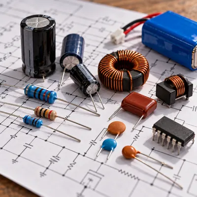
Inductors appear in every scale of electrical engineering: tiny surface-mount chokes on a circuit board, filter inductors in power supplies, line reactors in front of variable-frequency drives and shunt reactors weighing tens of tonnes at transmission substations. Because inductors and transformers both consist of coils on magnetic cores, they are often confused, and some devices, like coupled inductors and autotransformers, blur the line further.
This explainer covers the inductor definition, its electrical symbol and units, how current across an inductor behaves, how inductors are used in circuits and power systems, and exactly how an inductor differs from a transformer. It is written for students, electronics engineers moving into power, and buyers who see reactors on a single-line diagram and want to know what they do.
What Is an Inductor? Definition and Meaning
An inductor is a two-terminal passive electrical component that stores energy in a magnetic field when current flows through it and resists changes in that current. In physics terms, its defining property is inductance: the ratio of magnetic flux linkage to the current producing it, L = N × Φ / I.
When current through an inductor coil increases, the growing magnetic field induces a voltage that opposes the increase (Lenz's law). When current falls, the collapsing field induces a voltage that tries to keep current flowing. The inductor therefore acts like electrical inertia: it smooths current and resists sudden change.
For a coil wound on a core, inductance depends on geometry and material:
L = N² × μ0 × μr × A / l
where N is the number of turns, A the core cross-section, l the magnetic path length, μ0 = 4π × 10⁻⁷ H/m and μr the core's relative permeability. Doubling the turns quadruples the inductance.
Example of an inductor
An air-core coil of 200 turns, 20 mm diameter and 50 mm long has A = π × 0.01² = 3.14 × 10⁻⁴ m², so L = 200² × 4π × 10⁻⁷ × 3.14 × 10⁻⁴ / 0.05 ≈ 0.32 mH (ignoring end effects). Putting a ferrite core inside, with effective μr of a few hundred, would raise this by roughly that factor, until the core saturates. Saturation, driven by flux density, is explained in our magnetic flux density guide.
Inductor Symbol and Circuit Diagrams
The inductor circuit symbol is a series of loops or humps representing coil turns. Variations indicate the core type:
| Symbol description | Meaning | Where you see it |
|---|---|---|
| Plain series of loops (or arcs) | Air-core inductor | RF circuits, schematic default |
| Loops with two solid parallel lines | Iron or laminated-steel core | Power chokes, reactors |
| Loops with dashed parallel lines | Ferrite or powdered-iron core | Switch-mode power supplies |
| Loops with an arrow through them | Variable inductor | Tuning circuits |
| Rectangle with a coil designation (IEC 60617 alternative) | Reactor in single-line diagrams | Substation drawings |
Inductors are labeled L with a number (L1, L2) on schematics. In power single-line diagrams, reactors are often drawn as a single semicircular loop or a coil symbol with the rating beside it, for example “XL 6%” or “20 Mvar”.
The transformer symbol is two coils facing each other, sometimes with core lines between them; the visual difference is simply whether there is one winding or more. Our basic component symbols and electrical symbols guide show the full IEC and IEEE symbol sets, and the transformer symbol guide covers winding and core variants side by side.
Inductor Units: Henries, Millihenries and Microhenries
The SI unit of inductance is the henry (H). One henry is the inductance in which a current changing at one ampere per second induces one volt: 1 H = 1 V·s/A = 1 Wb/A.
| Unit | Value | Typical application |
|---|---|---|
| Nanohenry (nH) | 10⁻⁹ H | RF matching, PCB trace inductance, busbar stray inductance |
| Microhenry (μH) | 10⁻⁶ H | Switch-mode converter inductors, EMI filters |
| Millihenry (mH) | 10⁻³ H | Audio crossovers, drive line reactors, harmonic filter reactors |
| Henry (H) | 1 H | Smoothing chokes, MV and HV shunt reactors, arc-suppression coils |
In power engineering, reactors are usually specified by reactance in ohms or percent impedance rather than henries, because reactance is what sets voltage drop and fault current. The conversion is L = XL / (2πf).
Inductors in series add directly, L = L1 + L2 (with no mutual coupling). In parallel, they combine like resistors: 1/L = 1/L1 + 1/L2. If coils are magnetically coupled, mutual inductance M must be included: L = L1 + L2 ± 2M. That coupling term is where inductors begin to behave like transformers.
How Does Current Behave Across an Inductor?
The defining equation of an electrical inductor is:
v = L × di/dt
Three consequences follow, and they explain most of the purpose of an inductor in circuits.
1. Current cannot change instantly
An instantaneous step in current would require infinite voltage. When a DC voltage V is applied through a resistance R, current rises exponentially: i(t) = (V / R) × (1 − e^(−t/τ)), with time constant τ = L / R. A 0.5 H coil with 10 Ω resistance has τ = 50 ms and reaches about 99% of final current after 5τ, or 250 ms.
2. Inductors store energy
Energy stored is W = ½ × L × I². A 2 mH inductor carrying 20 A stores 0.5 × 0.002 × 400 = 0.4 J. If that current is interrupted suddenly, the energy appears as a voltage spike, which is why relay coils need flyback diodes and why interrupting inductive circuits stresses switchgear contacts.
3. Current lags voltage in AC circuits
With sinusoidal voltage, current through an ideal inductor lags by 90°. The opposition to AC is inductive reactance:
XL = 2π × f × L
A 10 mH inductor gives 2π × 60 × 0.010 = 3.77 Ω at 60 Hz. Reactance rises with frequency, so inductors pass DC and low frequencies while blocking harmonics and high-frequency noise. Inductive loads also draw reactive power, explained in our apparent, reactive and real power guide and our power factor explainer.
Inductor vs Transformer: What Is the Difference?
Both devices rely on coils and magnetic cores, but they are designed for opposite goals. An inductor is built to store energy in its magnetic field; a transformer is built to transfer energy between windings while storing as little as possible.
| Feature | Inductor | Transformer |
|---|---|---|
| Windings | One (or coupled windings on one magnetic path) | Two or more, magnetically coupled |
| Function | Store energy, filter, limit current | Change voltage and current, isolate circuits |
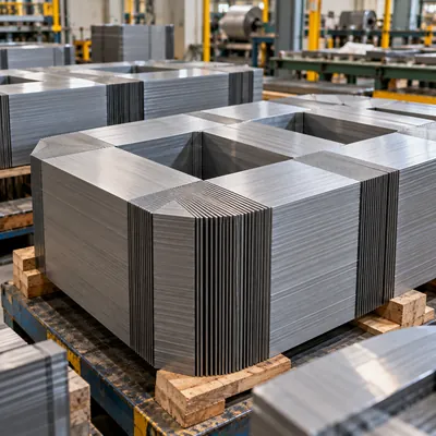
| Core | Often gapped to store energy and avoid saturation | Closed, ungapped, highest permeability |
| Magnetizing current | Equal to load current | Small, typically under 1–2% of rated current |
| Flux set by | Current through the coil | Applied voltage |
| Key rating | Inductance (H) or reactance (Ω, %), current | kVA, voltage ratio, impedance |
| Power-system standard | IEC 60076-6, IEEE C57.21, IEEE C57.16 | IEC 60076-1, IEEE C57.12.00 |
A useful way to see the link: in the transformer equivalent circuit, the magnetizing branch is an inductor, and the leakage reactances in series with each winding are inductors too. The transformer's percent impedance is largely leakage inductance, which limits fault current in exactly the way a series reactor does. Our transformer equivalent circuit article shows this model in detail.
Flyback converters and coupled inductors sit between the two: they have multiple windings like a transformer but store energy in a gapped core like an inductor.
Inductors in Electrical Power Systems
In utility and industrial networks, large inductors are called reactors. Each type addresses a specific problem:
- Line and load reactors: 3–5% impedance reactors in front of or after VFDs reduce harmonic current, limit dv/dt and protect drives from supply transients.
- Current-limiting series reactors: installed in feeders or bus ties to reduce prospective fault current so switchgear ratings are not exceeded. See our fault current calculation guide.
- Shunt reactors: connected line-to-ground on long transmission lines and cables to absorb capacitive reactive power and control voltage rise at light load.
- Harmonic filter reactors: paired with capacitors to form tuned filters, for example tuned near the 5th harmonic.
- Neutral grounding reactors and arc-suppression coils: connected from a transformer neutral to ground to limit or compensate earth-fault current. Resistive alternatives are covered in our neutral earthing resistor guide.
- Smoothing reactors: on DC links and rectifier outputs to reduce ripple.
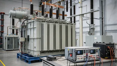
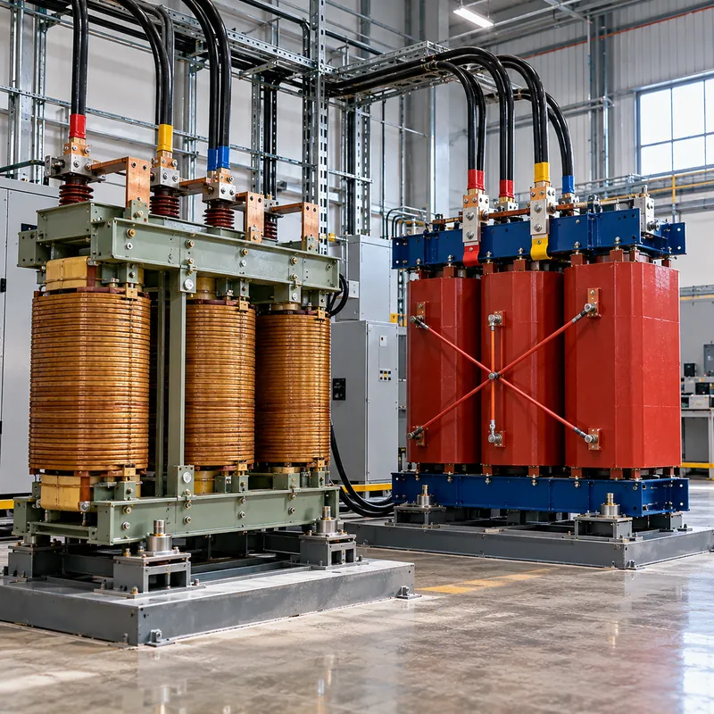
Dry-type air-core reactors are common for series and filter duty because they cannot saturate; oil-immersed gapped-core designs dominate shunt reactors at transmission voltages.
Worked Example: Sizing a Drive Line Reactor
A 480 V, 60 Hz, three-phase VFD draws 100 A. The supplier recommends a 3% line reactor. What inductance is needed?
- Phase voltage:
480 / √3 = 277 V. - Base impedance:
Zbase = Vphase / I = 277 / 100 = 2.77 Ω. - Required reactance at 3%:
XL = 0.03 × 2.77 = 0.0831 Ω. - Inductance:
L = XL / (2πf) = 0.0831 / 377 = 0.220 mHper phase. - Voltage drop at full load:
100 × 0.0831 = 8.3 Vper phase, 3% of 277 V. - Stored energy per phase at peak current (141 A):
0.5 × 0.000220 × 141² ≈ 2.2 J.
The reactor must also be rated for the RMS current including harmonics and for the fundamental-frequency voltage drop, and it should be checked for saturation at peak fault current. A drive isolation transformer with 5–6% impedance achieves a similar harmonic-limiting effect while also providing galvanic isolation and voltage change, which is one practical example of a transformer doing an inductor's job. Our power conversion transformer guide covers that alternative.
Next Steps: Specifying and Sourcing
If your project needs a reactor, specify inductance or percent reactance, rated current (including harmonic content), system voltage and BIL, short-time current, cooling and enclosure, and the applicable standard: IEC 60076-6 internationally, IEEE C57.21 for shunt reactors or IEEE C57.16 for dry-type series reactors.
MARS does not manufacture stand-alone inductors or reactors. We design and build power transformers up to 31,500 kVA and 110 kV class, distribution transformers and compact substations, and we can specify transformer impedance to provide part of the fault-current limiting or harmonic-damping duty a series reactor would otherwise perform. Where a project combines transformers with MV and LV switchgear, our engineers can review the single-line diagram to see where impedance is best placed. Send details through the quote request form.
Frequently asked questions
What is the purpose of an inductor?
An inductor stores energy in its magnetic field and opposes changes in current. That makes it useful for smoothing current in power supplies, filtering harmonics and noise, limiting fault or inrush current, storing energy in switch-mode converters and tuning resonant circuits with capacitors.
What is the unit of inductance?
The unit of inductance is the henry, symbol H. One henry produces one volt when current changes at one ampere per second. Practical inductors are often specified in millihenries (mH) or microhenries (μH), while power-system reactors are usually rated in ohms or percent reactance.
What does the inductor symbol look like?
The inductor symbol is a row of loops or humps representing coil turns. Two solid parallel lines beside the loops indicate an iron core, dashed lines a ferrite core, and an arrow through the coil a variable inductor. Schematics label inductors L1, L2 and so on.
Is a transformer just two inductors?
Physically it is two or more coupled coils, but it behaves differently. A transformer's windings share a closed core so that nearly all flux links both, and its job is to transfer energy. Each winding has self-inductance, yet the magnetizing current is small and little energy is stored compared with a dedicated inductor.
Why does current lag voltage in an inductor?
Because voltage across an inductor is proportional to the rate of change of current. With a sine wave, the rate of change is greatest when current crosses zero, so voltage peaks a quarter cycle before current does. In an ideal inductor, current lags voltage by exactly 90 degrees.
How do you calculate inductive reactance?
Use XL = 2π × f × L, with f in hertz and L in henries. For example, a 50 mH inductor at 50 Hz has XL = 2 × 3.1416 × 50 × 0.05 = 15.7 Ω. Reactance increases with frequency, so the same inductor presents 18.8 Ω at 60 Hz.
Written and reviewed by the MARS application engineering team in Shanghai, who specify and test transformers, switchgear, substations and battery storage for projects in 40+ countries. Last updated .
Tags: inductor inductor symbol inductor units inductor definition inductors in circuits