Key takeaways
- The primary winding connects exclusively to the input energy source, whilst the secondary delivers transformed voltage and current to the downstream load.
- Turns ratio in three-phase transformers depends strictly on the vector group configuration (such as Dyn11), where phase voltages govern turn relationships rather than raw line-to-line values.
- Loop-feed distribution units utilise dual primary bushings per phase (H1A/H1B) to permit uninterrupted pass-through of medium-voltage power to adjacent substations.
- Secondary load currents reflect onto the primary side in inverse proportion to the turns ratio, preserving the balance of primary and secondary ampere-turns under Lenz's law.
- Impedance reflects across windings by the square of the phase turns ratio, determining prospective fault currents on both sides according to IEC 60076-5.
Quick answer: In an electrical power transformer, the primary winding connects to the alternating power source to produce an alternating magnetic core flux, whilst the secondary winding couples with that flux to deliver stepped-up or stepped-down voltage to an electrical load. Their relationship is governed by Faraday's law of induction, where voltage and current scale precisely with the turns ratio.
Understanding the interaction between transformer primary and secondary circuits is foundational to designing reliable medium-voltage (MV) and low-voltage (LV) systems. Whether specifying industrial unit substations, renewable collector circuits, or commercial power networks, network engineers must evaluate how winding configurations, vector phase displacements, and impedance reflection dictate operating performance. For network layouts incorporating ring or parallel topologies, evaluating the radial feed vs loop feed architecture becomes essential when configuring the primary side termination.
Transformer Physics: How Energy Couples Between Primary and Secondary
Transformer physics relies on electromagnetic induction across magnetically coupled windings rather than direct galvanic conduction. When an alternating voltage Vp is applied to the primary winding, it draws an excitation current consisting of magnetising current and core-loss components. According to Faraday's law of electromagnetic induction, this creates a time-varying magnetic flux Φ within the laminated silicon-steel core, described by:
e = -N (dΦ/dt)
Because the high-permeability magnetic core channels virtually all flux lines, the alternating flux links directly with the secondary winding. In accordance with Lenz's law, the induced electromotive force (EMF) in the secondary generates a counter-flux as soon as a closed load circuit allows secondary current Is to flow. To maintain core flux equilibrium at a constant applied voltage, the primary circuit draws an additional load-balancing current Ip' from the source.
This balance requires the net magnetomotive force (MMF) to remain essentially constant, satisfying the ampere-turn relationship NpIp' = NsIs. Neglecting core excitation losses, the instantaneous power transferred across the primary and secondary windings remains equal, establishing the inverse proportionality between voltage transformation and current transformation.
Defining the Primary Side of Transformer Circuits vs Secondary Loads
The primary side of transformer equipment is strictly defined by the direction of real power flow rather than nominal voltage level. In step-down distribution installations, the medium-voltage terminal block (designated H1, H2, H3 under IEEE C57.12.00 or 1U, 1V, 1W under IEC 60076-1) serves as the primary side. Conversely, in generation stations, solar farms, and battery energy storage facilities, the low-voltage terminal connected to the inverter or generator serves as the primary, stepping power up to grid transmission levels.
Operating conditions on the primary side differ substantially from the secondary:
- Operating voltage and insulation: The primary side of transformer equipment connected to MV distribution must withstand severe Basic Impulse Insulation Levels (BIL), typically 75 kV to 125 kV BIL for 11 kV to 33 kV systems, in contrast to standard 1.1 kV or 3 kV insulation classes on 400 V secondaries.
- Switching transients: The primary side experiences steep-fronted transient overvoltages resulting from vacuum circuit breaker operations and lightning surges, requiring coordinated surge arresters directly adjacent to primary bushings as outlined in our medium voltage transformer guide.
- Fault clearing response: Upstream utility protection relies on primary overcurrent relays and fuses to clear secondary phase-to-phase and phase-to-earth faults, which are reflected to the primary winding in accordance with the transformer connection geometry.
Turns Ratio and Current Calculations: A Worked Engineering Example
Calculating the operational parameters between transformer primary and secondary circuits requires precise consideration of three-phase winding configurations and vector groups. Consider a standard 1,000 kVA, 11,000 V to 415 V distribution transformer connected in a Dyn11 vector group (delta primary, star secondary with neutral) operating at 50 Hz with an impedance (%Z) of 5.0%.
Step 1: Calculate full-load line currents
Primary full-load current (Ip,line):
Ip,line = S / (√3 × Vp,line) = 1,000,000 VA / (1.73205 × 11,000 V) = 52.49 A
Secondary full-load current (Is,line):
Is,line = S / (√3 × Vs,line) = 1,000,000 VA / (1.73205 × 415 V) = 1,391.26 A
Step 2: Calculate the phase turns ratio (a)
Because the primary is delta-connected, the primary phase voltage equals the line-to-line voltage: Vp,phase = 11,000 V. The secondary is star-connected, so the secondary phase voltage is line-to-neutral: Vs,phase = 415 V / √3 = 239.60 V.
a = Vp,phase / Vs,phase = 11,000 V / 239.60 V = 45.91
Step 3: Calculate reflected impedance and prospective symmetrical fault current
Impedance reflects across the windings according to the square of the turns ratio: Zp = a2 × Zs. For a 5.0% impedance transformer, the prospective symmetrical short-circuit current on the secondary terminals (assuming an infinite primary source bus) is:
Isc,s = Is,line / (%Z / 100) = 1,391.26 A / 0.05 = 27,825 A (27.83 kA)
The corresponding symmetrical fault current reflected on the primary side is:
Isc,p = Ip,line / (%Z / 100) = 52.49 A / 0.05 = 1,049.8 A (1.05 kA)
These figures directly dictate the minimum breaking capacity of secondary switchgear and the required curve settings for primary protective relays, as detailed in our guide to transformer protection.
Loop-Feed Distribution: Dual Bushings on the Primary Side
In loop-feed distribution transformers, the primary side of transformer tanks features two sets of medium-voltage bushings per phase (designated H1A/H1B, H2A/H2B, H3A/H3B) rather than the single set found on radial units. These bushings are connected internally to an integrated copper busbar assembly, forming a loop-through path rated to carry the full continuous feeder current (typically 200 A or 600 A under IEEE C57.12.34).
This primary loop configuration delivers specific functional advantages in underground distribution networks:
- Sectionalisation: An internal two-position or four-position load-break oil-immersed switch allows operators to isolate the local core and coils while maintaining power continuity to downstream substations on the loop.
- Redundant supply: Power can be delivered from either incoming direction (Loop A or Loop B), enabling fast service restoration during cable faults without de-energising secondary loads.
- Deadfront safety: MV primary bushings utilise 200 A loadbreak elbow connectors or 600 A deadbreak interfaces, enclosing all live high-voltage parts in earthed, shielded rubber mouldings.
Secondary configurations in loop-feed pad-mounted units remain functionally identical to radial units, terminating at low-voltage spade terminals (X1, X2, X3, X0) inside a separate, mechanically isolated cable compartment.
Primary vs Secondary Technical Comparison
Designing and installing substation equipment requires clear distinction between primary and secondary engineering parameters. The following comparison outlines standard technical boundaries for an 11 kV to 415 V, 1,000 kVA mineral-oil distribution unit built to IEC 60076-1:
| Engineering Parameter | Primary Side (HV) | Secondary Side (LV) | Standard Reference |
|---|---|---|---|
| Nominal Voltage | 11,000 V (Phase-to-Phase) | 415 V / 240 V (Three-Phase Four-Wire) | IEC 60038 Table 1 |
| Full-Load Rated Current | 52.5 A | 1,391.3 A | IEC 60076-1 clause 5.4 |
| Basic Impulse Insulation (BIL) | 75 kV or 95 kV peak | 10 kV to 30 kV peak | IEC 60076-3 Table 2 |
| Conductor Cross-Section | Smaller area, higher turn count | Massive copper/aluminium busbars or foil | IEC 60076-5 clause 4 |
| Winding Connection | Delta (Δ) - 3 terminals | Star (Y) with earthed neutral (YN) - 4 terminals | IEC 60076-1 clause 6 |
| Tapping Provision | Off-circuit tap changer (±2 × 2.5%) | Fixed nominal winding | IEC 60076-1 clause 7 |
| Earthing Configuration | Ungrounded / earthed via source system | Directly solidly grounded system neutral (MEN/TN-C-S) | BS 7671 / NFPA 70 |
| Terminal Type | Elbow wells or porcelain bushings | NEMA 4-hole to 12-hole spade terminals | IEEE C57.12.34 |
Testing Verification for Transformer Primary and Secondary Windings
Factory acceptance testing (FAT) and site commissioning must verify the structural and electromagnetic integrity of both windings prior to energisation. Testing engineers execute a structured sequence of diagnostic procedures to confirm that primary and secondary systems match design tolerances:
- Voltage Ratio and Phase Displacement Test: In accordance with IEC 60076-1 clause 11.3, test equipment applies a reduced voltage across the primary terminals and measures the corresponding secondary output across all tap positions. The measured turns ratio must not deviate by more than ±0.5% from the specified nameplate ratio.
- Winding Resistance Measurement: Measured using a high-precision four-wire Kelvin micro-ohmmeter to ensure balance between phases and detect cold-joint soldering defects, corrected to 75°C or 85°C reference temperature.
- Insulation Resistance and Polarisation Index: Applied at 2.5 kV or 5 kV DC between primary and secondary, primary to tank earth, and secondary to tank earth, verifying dielectric soundness as detailed in our guide on how to test a transformer.
- Short-Circuit Impedance and Load Loss: Secondary terminals are solidly short-circuited with rated current circulated through the primary side to measure copper losses and verify %Z compliance under IEC 60076-1 clause 11.4.
Engineering Checklist for Specifying Transformer Primary and Secondary Parameters
Procurement documents and tender specifications should explicitly capture both primary and secondary design limits to eliminate sizing discrepancies during manufacturing. Before submitting an inquiry or finalizing an electrical schedule, ensure the following technical parameters are verified:
- Source parameters: Supply voltage, grid frequency (50 Hz or 60 Hz), prospective short-circuit level (MVA or kA), and earthing regime (isolated, resistance grounded, or solid).
- Primary winding: Voltage class, required BIL rating, Delta or Star connection, tap changer configuration (Off-Circuit Tap Changer or On-Load Tap Changer, range, and percentage step steps).
- Secondary winding: Nominal load voltage at no-load and full-load, neutral bushing sizing (minimum 100% or 200% rated for harmonic content), and vector displacement (e.g., Dyn11, YNd1).
- Distribution interface: Primary feed style (radial feed vs loop feed), bushing arrangement (deadfront elbow wells vs open porcelain), and mechanical cable clearance dimensions.
- Impedance and losses: Specified %Z within standard tolerance bands (±10% per IEC 60076-1) and maximum guaranteed no-load (core) and load (winding) losses.
Next steps: specifying and sourcing
When preparing specifications for medium-voltage infrastructure, procuring equipment that precisely matches your primary distribution voltages and secondary load profiles prevents costly operational bottlenecks. Our engineering team reviews site single-line diagrams, short-circuit requirements, and loop-feed configurations to provide fully compliant, factory-tested units built to IEC 60076 or IEEE C57 standards. Explore our range of pad-mounted transformers, oil-immersed transformers, and complete prefabricated transformer substations, or visit our quotation request page to submit your technical schedule directly to our design engineers.
Frequently asked questions
What is the difference between transformer primary and secondary?
The primary winding receives alternating electrical energy directly from the input power source, whereas the secondary winding delivers transformed voltage and current to downstream loads. The primary creates magnetic core flux; the secondary converts that magnetic flux into usable electrical energy.
Can the secondary winding be used as the primary side?
Yes, transformers are bidirectional electromagnetic devices capable of back-feeding. However, when using a secondary winding as the primary input, engineers must compensate for internal voltage regulation drops and verify that inrush current characteristics do not trip upstream protection.
Why does the primary side of a distribution transformer use thinner wire?
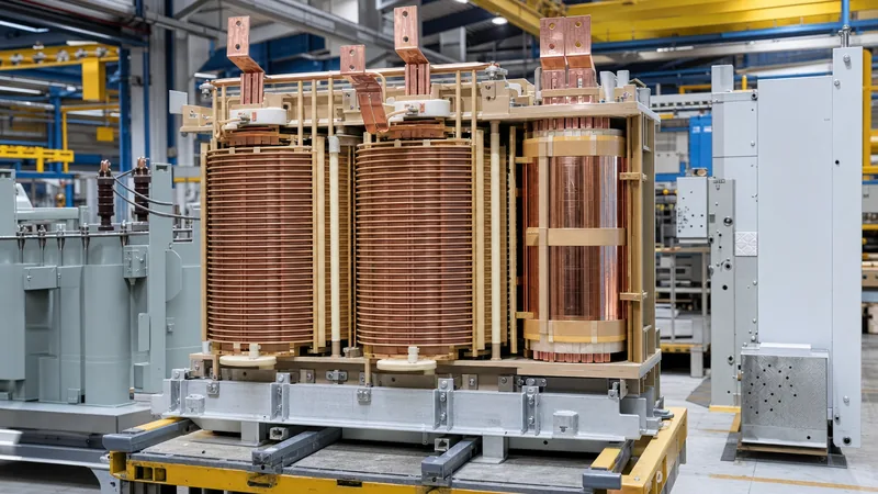
The primary winding operates at a higher voltage, which results in a proportionately lower full-load current under the law of conservation of energy. Because conductor cross-section is sized for continuous current carrying capacity, the high-voltage primary requires significantly less copper area than the high-current secondary.
How do you identify primary and secondary terminals on a transformer?
Primary terminals on standard medium-voltage distribution transformers are designated with H markings (H1, H2, H3 under IEEE) or 1-prefixes (1U, 1V, 1W under IEC) and feature larger insulating bushings. Secondary terminals are labelled with X markings (X1, X2, X3, X0) or 2-prefixes (2U, 2V, 2W, 2N).
What happens to the primary current when the secondary load increases?
When secondary load increases, increased secondary current creates a demagnetising magnetic flux within the core. Under Lenz's law, the primary winding must immediately draw a corresponding increase in load current from the electrical supply to re-establish the constant core flux equilibrium.
Why is the primary side commonly connected in Delta and secondary in Star?
A Delta-Star (Dyn11) configuration traps third-harmonic currents within the closed primary delta loop, preventing harmonic distortion from spreading upstream to the power grid. Meanwhile, the secondary star connection provides a stable neutral conductor (X0) to support both 400 V three-phase and 230 V single-phase loads.
Tags: transformer primary and secondary transformer physics primary side of transformer distribution transformers turns ratio


