Key takeaways
- A medium voltage transformer operates between 1 kV and 36 kV, stepping primary utility distribution down to standard utilisation voltages.
- Standard medium voltage transformer sizes range from 75 kVA up to 3,150 kVA for commercial and industrial pad-mounted or unit substation installations.
- Loop-feed configurations provide dual-source switching flexibility, significantly reducing downtime compared to radial-feed installations.
- Short-circuit withstand sizing requires calculating symmetrical fault current using rated impedance percentage under IEC 60076-5 or IEEE C57.12.00 Table 5.
- Medium voltage control transformers provide regulated 120 V or 240 V auxiliary power inside switchgear for trip coils, relays, and motor mechanisms.
Quick answer: A medium voltage transformer is an electrical distribution asset that converts voltages between 1 kV and 36 kV down to low-voltage utilisation levels (typically 208 V, 400 V, or 480 V) or steps generation voltages up for distribution. It provides galvanic isolation, voltage regulation, and fault level management for industrial plants, utilities, renewable facilities, and commercial buildings.
In electrical power distribution, an mv transformer acts as the critical bridge between utility distribution infrastructure and end-user switchgear. Specifying the correct unit demands careful evaluation of insulation mediums, winding configurations, winding loss figures, thermal rise limits, and operational topology. Selecting an inappropriate unit risks premature thermal failure, excessive parasitic losses, or high replacement costs during facility expansion.
Standard medium voltage transformer sizes and ratings
Standard medium voltage transformer sizes follow standardised capacity increments to harmonise with utility grid standards and switchgear ratings. Operating voltages on the primary winding typically span 4.16 kV, 11 kV, 13.8 kV, 22 kV, 33 kV, and 34.5 kV, while secondary voltages supply 400 V in IEC jurisdictions or 480Y/277 V and 208Y/120 V under ANSI standards.
Selecting an standard size ensures shorter lead times, interchangeability, and verified short-circuit impedance values. The table below outlines standard three-phase industrial and commercial distribution ratings, standard impedance percentages per IEEE C57.12.00 Table 5, and their primary applications.
| Rated Power (kVA) | Typical Primary (kV) | Typical Secondary (V) | Standard Impedance (%Z) | Primary Application |
|---|---|---|---|---|
| 75 to 225 | 4.16 – 13.8 | 208Y/120, 480Y/277 | 2.0% – 3.5% | Small commercial facilities, remote pumping stations |
| 300 to 500 | 4.16 – 24.9 | 400, 480Y/277 | 4.0% – 5.0% | Commercial office parks, light industrial fabrication |
| 750 to 1,500 | 11.0 – 34.5 | 400, 480Y/277 | 5.75% | Manufacturing plants, data centres, distribution centres |
| 2,000 to 3,150 | 13.8 – 34.5 | 480, 690, 4,160 | 5.75% – 6.5% | Heavy process industries, large BESS, unit substations |
| 4,000 to 10,000 | 22.0 – 36.0 | 4,160, 6,600, 11,000 | 6.5% – 8.0% | Primary industrial substations, mining sites |
To examine three-phase core structures, winding groupings, and vector arrangements, refer to our detailed 3-phase transformer guide.
Liquid-immersed vs cast resin dry-type mv transformer selection
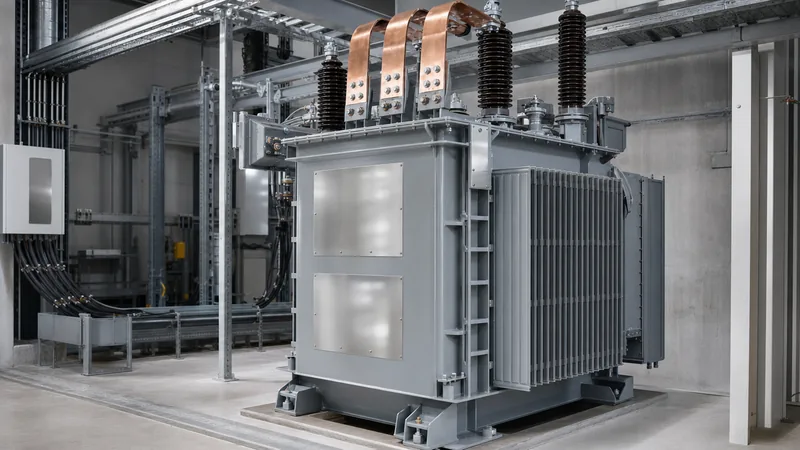
The choice between a liquid-immersed and a cast resin dry-type mv transformer depends primarily on indoor safety codes, environmental sensitivity, and installation physical footprints. Liquid-immersed units use mineral oil or less-flammable natural/synthetic esters (K-class fluids per IEC 61039) for dielectric insulation and convective heat transfer.
Mineral oil units deliver exceptional thermal longevity and lower purchase capital costs, making them the default selection for outdoor pad-mounted substations. However, when specifying an installation inside a multi-storey building, underground vault, or process plant, local fire codes often require costly fire-separation barriers or automatic deluge systems. Alternatively, high-fire-point ester fluids raise the fire point above 300 degrees Celsius, satisfying NEC Section 450.23 clearances.
Cast resin dry-type units encapsulate high-voltage and low-voltage windings in epoxy under vacuum, eliminating liquid containment basins entirely. They operate safely in indoor switchgear rooms and tunnels where chemical leakage or flammability presents unacceptable operational hazards. For complete selection criteria regarding air-cooled and cast coil designs, explore our dry-type transformer guide.
Loop feed vs radial feed medium voltage transformer configurations
A loop-feed medium voltage transformer incorporates incoming and outgoing high-voltage bushings connected via internal copper buswork to enable looping of primary feeders across multiple substations. This configuration is widely deployed across industrial campuses, underground utility networks, and utility-scale solar or storage plants.
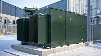
In contrast to a radial system, which relies on a single utility line that drops all downstream loads during an upstream cable fault, loop feeding allows power to enter from either direction. When paired with an internal or external four-position load-break switch, operators can isolate any faulted cable segment while back-feeding the transformer from an alternate source. When integrating these units into compact pad enclosures, engineers frequently specify pad-mounted transformers fitted with dead-front elbow terminators rated for 200 A or 600 A under IEEE 386. For a complete system architecture comparison, review our guide on radial feed vs loop feed distribution.
Medium voltage control transformers and instrument systems
Medium voltage control transformers, often designated as control power transformers (CPTs) or auxiliary voltage transformers, step primary medium voltage levels down to 120 V, 240 V, or 110 V to energise switchgear protection circuits, relay logic, and circuit breaker charging mechanisms.
Unlike bulk distribution units, a control-grade medium voltage transformer is engineered for high thermal reserve capacity and exceptional voltage regulation under instantaneous peak inrush loads. Closing an MV circuit breaker solenoid or charging spring motor draws an inductive inrush up to ten times the continuous volt-ampere rating of the auxiliary circuit. If the control transformer exhibits excessive internal impedance, secondary voltage drops below the minimum operating threshold of protection relays (typically 80% to 85% of nominal per IEC 60255), leading to breaker trip failures.
These units conform to instrument transformer standards such as IEEE C57.13 or IEC 61869-3. They are commonly installed within medium-voltage switchgear bays with draw-out carriages and integrated primary current-limiting fuses to facilitate safe maintenance disconnection. For detailed protection architectures, refer to our MV switchgear engineering guide.
Sizing calculation and impedance verification
Calculating the continuous load capacity and prospective short-circuit fault current of a medium voltage transformer ensures switchgear busbars and downstream protective devices are rated correctly. An undersized transformer overheats under peak operating periods, while underestimating available fault currents risks catastrophic switchgear rupture.
Consider a manufacturing facility with a design maximum continuous demand of 1,280 kVA operating from a 13.8 kV distribution line, stepping down to 480 V (three-phase, 60 Hz). Applying a 20% growth reserve factor establishes the minimum transformer capacity:
$$S_{target} = 1280 \times 1.20 = 1536\text{ kVA}$$
Select the nearest standard transformer rating: 1,500 kVA or 2,000 kVA. If 1,500 kVA is selected with forced-air (FFA/ONAF) provisions to handle short-term excursions, calculate rated secondary full-load current ($I_{FLC}$):
$$I_{FLC} = \frac{S}{\sqrt{3} \times V_{LL}} = \frac{1,500,000\text{ VA}}{\sqrt{3} \times 480\text{ V}} = 1804.22\text{ A}$$
According to IEEE C57.12.00 Table 5, the standard factory impedance (%Z) for a 1,500 kVA unit with a 13.8 kV primary is 5.75% (tolerance $\pm 7.5\%$ per IEC 60076-1 clause 10). Assuming an infinite utility source bus on the 13.8 kV side, determine the maximum symmetrical short-circuit current ($I_{SC}$) on the secondary terminals:
$$I_{SC} = \frac{I_{FLC}}{Z_{pu}} = \frac{1804.22\text{ A}}{0.0575} = 31,377.7\text{ A} \approx 31.38\text{ kA}$$
This calculation verifies that the low-voltage switchboard main breaker must feature an interrupting rating of at least 35 kA (or 42 kA to 50 kA standard industrial rating increments) to withstand dead-short conditions at the transformer secondary terminals safely.
Factory evaluation: vetting medium voltage transformer manufacturers
Auditing medium voltage transformer manufacturers requires evaluating design compliance, internal winding insulation practices, core steel grades, and formal factory acceptance testing (FAT). Industrial buyers must look beyond headline capital equipment pricing to examine total cost of ownership, which is dominated by no-load (core) and load (copper) losses evaluated over a 25-year service life.
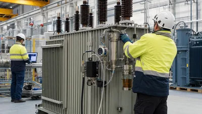
Factory testing must be conducted in strict accordance with IEC 60076-1 or IEEE C57.12.90. To verify manufacturing build quality prior to shipment, your inspection team should follow a strict FAT verification protocol:
- Winding resistance measurements: Verify copper or aluminium DC resistance balance across all tap positions using a micro-ohmmeter; phase-to-phase deviations must remain below 1.0%.
- Voltage ratio and vector group verification: Confirm voltage ratios across all no-load or on-load tap positions within 0.5% tolerance per IEC 60076-1 clause 10.
- Insulation power factor and resistance: Conduct Megger insulation resistance testing (HV-LV, HV-Ground, LV-Ground) at 2.5 kV or 5.0 kV DC, ensuring insulation power factor ($tan \,\delta$) remains under 0.5% at 20 degrees Celsius.
- No-load loss and excitation current test: Measure no-load losses at 100% and 110% rated secondary voltage to detect core steel laminations defect or high harmonic magnetising currents.
- Short-circuit impedance and load loss: Excite primary windings at rated frequency with low-voltage shorted to verify impedance compliance within standard tolerances.
- Dielectric withstand and impulse tests: Execute separate-source AC withstand (power frequency) and basic impulse insulation level (BIL) lightning impulse tests (e.g., 95 kV BIL for a 13.8 kV system) per IEC 60076-3.
For modular layouts integrating medium-voltage gear directly with low-voltage sections, explore our engineering reference on unit substation engineering.
Next steps: specifying and sourcing
When preparing your technical requisition for a medium voltage transformer, assemble a complete inquiry package that eliminates ambiguity. Ensure your request includes: rated capacity (kVA/MVA), primary and secondary voltages, winding connection vector group (e.g., Dyn11 or Delta-Wye), BIL withstand levels, installation altitude, environmental temperature extremes, and impedance limitations.
Review our factory-engineered oil-immersed distribution transformers for outdoor applications, explore high-efficiency dry-type transformers for indoor substations, or examine turnkey prefabricated substations. When your project demands customized winding configurations, specific loss evaluation formulas, or rapid delivery schedules, submit your single-line diagrams directly to our engineering team through our transformer quote portal to receive factory-direct sizing calculations and commercial proposals.
Frequently asked questions
What is the voltage range of a medium voltage transformer?
A medium voltage transformer operates within primary or secondary system voltages between 1,000 V (1 kV) and 35 kV or 36 kV according to IEC and IEEE standards. Equipment operating above 36 kV is classified as high voltage (HV), while equipment below 1 kV is classified as low voltage (LV).
What is the difference between loop feed and radial feed medium voltage transformers?
A loop feed transformer includes dual sets of high-voltage bushings connected internally, allowing the unit to receive power from two directions in a ring distribution network. A radial feed transformer features only one set of high-voltage bushings and connects to a single dead-end power feeder.
How do you calculate the secondary fault current of a medium voltage transformer?
Divide the transformer rated full-load secondary current by its per-unit impedance. For instance, a 1,500 kVA transformer at 480 V produces 1,804 A full load; dividing by a 0.0575 per-unit impedance (5.75%) results in approximately 31.38 kA symmetrical short-circuit current.
What are the standard medium voltage transformer sizes for industrial facilities?
Standard industrial ratings include 500 kVA, 750 kVA, 1,000 kVA, 1,500 kVA, 2,000 kVA, and 2,500 kVA. Sizing follows established standard increments to match standard low-voltage switchboard breaker frames and utility distribution limits.
Why are medium voltage control transformers required in switchgear?
Medium voltage control transformers step primary bus voltage down to 120 V or 240 V to provide auxiliary power for protective relays, indicator lamps, and breaker trip/close coils. They are built with low internal impedance to prevent voltage collapse during high-inrush breaker operating cycles.
When should cast resin dry-type transformers be specified over oil-filled units?
Cast resin dry-type transformers should be specified for indoor commercial installations, high-rise buildings, underground operations, and food-processing environments where mineral oil leakage or flammability presents unacceptable safety risks and environmental containment challenges.
Tags: medium voltage transformer mv transformer medium voltage transformer manufacturers medium voltage control transformers medium voltage transformer sizes