Key takeaways
- A wye delta transformer bank provides inherent suppression of third-harmonic currents by circulating them within the closed secondary delta loop.
- Connecting the primary neutral to system ground creates an unintentional grounding bank, risking transformer overheating during utility line-to-ground faults.
- A standard three-phase wye delta bank introduces a 30-degree phase shift between primary and secondary voltage vectors according to IEEE C57.12.00 and IEC 60076-1.
- Open wye open delta transformer banks operate with two single-phase units at 57.7 percent of the capacity of a full three-unit bank (86.6 percent of the two units combined rating).
- Before closing the secondary delta corner during commissioning, measuring near-zero volts across the final open junction is mandatory to prevent destructive short-circuit currents.
Quick answer: A wye delta transformer bank connects three single-phase transformers—or the windings of a three-phase unit—with a star (wye) primary and a delta secondary. This configuration delivers three-phase power, steps down medium distribution voltages efficiently, isolates third-harmonic voltages, and reliably serves heavy industrial motor loads alongside single-phase commercial services.
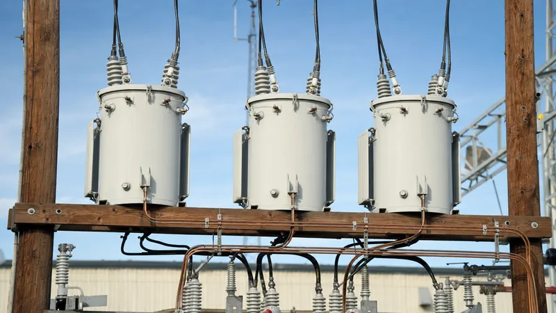
Substation engineers and utility distribution planners frequently construct a wye delta transformer bank using individual single-phase units mounted on poles or substation pads. This modular approach allows utilities to scale network capacity and quickly replace individual units upon failure. Proper implementation, however, requires a precise understanding of phase displacement, neutral grounding stability, and circulation currents. For related wiring symbols and connection schematics, see our transformer wiring schematic guide.
Engineering Architecture of a Wye Delta Transformer Bank
The core configuration of a wye delta transformer bank couples a high-voltage (HV) wye connection on the source side to a low-voltage (LV) delta connection on the load side. On the primary side, one terminal of each single-phase winding connects to an incoming phase (H1 to phases A, B, and C), while the opposite terminals (H2) join at a common star point. Because line-to-neutral voltage equals line-to-line voltage divided by the square root of three (VLN = VLL / √3), the primary winding insulation only needs to withstand line-to-neutral potential. This significantly reduces manufacturing costs at medium and high voltages, as detailed in our single-phase transformer guide.
On the secondary side, windings connect head-to-tail (X1 of one transformer to X2 of the adjacent unit) to establish a closed mesh. The secondary line voltage equals the transformer secondary coil voltage. Per IEEE C57.12.00 Table 5 and IEC 60076-1 clause 5.4, a standard delta-wye or wye-delta winding arrangement produces an angular displacement where the low-voltage vector either lags or leads the high-voltage vector by 30 electrical degrees. In North American utility practice, the standard connection results in the low-voltage phase lagging the high-voltage phase by 30 degrees (often designated as vector group Yd1 or Dyn1 under IEC standards).
Grounded vs Ungrounded Primary in a Wye Delta Bank
Determining whether to earth the primary neutral of a wye delta bank represents one of the most critical distribution protection decisions. If the primary star point of a wye delta bank is tied to the multi-grounded distribution neutral (MGN), the transformer bank acts as a zero-sequence ground source for the utility system. When an upstream single line-to-ground (SLG) fault occurs on the transmission or distribution feeder, zero-sequence current flows up through the grounded transformer neutral and circulates freely inside the closed secondary delta. This secondary circulation can rapidly overheat the transformer coils, even when the downstream load demand remains well below rated capacity.
Conversely, leaving the primary neutral floating (ungrounded) prevents the bank from acting as a grounding source and eliminates circulating fault currents during upstream phase-to-earth faults. However, an ungrounded primary neutral introduces a severe operational vulnerability: ferroresonance. When utility line crews use single-phase cutouts or switches to energise or de-energise the bank, capacitance between open cables or lines and the non-linear magnetising inductance of the ungrounded core can trigger high-magnitude, destructive overvoltages and neutral inversion. Consequently, modern engineering practice often favours ungrounded operation only when three-phase ganged vacuum circuit breakers or reclosers are installed to switch all three phases simultaneously.
Wye Delta Bank vs Wye Wye Bank and Open Wye Systems
Selecting between a wye delta configuration, a wye wye bank, or an open connection depends directly on load characteristics, harmonic profiles, and supply continuity requirements. While a wye-wye arrangement provides standard line-to-neutral voltages across all three phases without phase displacement, it requires a four-wire or five-legged core topology (or a tertiary delta winding) to suppress third harmonics and prevent neutral shift under unbalanced loads. A comparison of these structural topologies clarifies their application boundaries.
| Configuration Topology | Phase Displacement (deg) | Zero-Sequence & 3rd Harmonic Behaviour | Unbalanced Load Capability | Component Count |
|---|---|---|---|---|
| Wye-Delta Bank | 30° | Third harmonics circulate in delta; traps zero sequence | High; secondary maintains voltage symmetry | 3 single-phase units |
| Wye-Wye Bank (Grd-Grd) | 0° | Third harmonics enter neutral; potential telephone interference | Moderate; neutral shift if ground impedance is high | 3 single-phase units |
| Open Wye-Open Delta Bank | 30° (distorted) | Cannot trap zero sequence; voltage unbalance under load | Limited; strictly constrained by lagging unit | 2 single-phase units |
| Delta-Delta Bank | 0° | Third harmonics circulate in closed loops on both sides | High; handles heavy single-phase tap unbalance | 3 single-phase units |
As indicated in the table, the closed secondary delta provides superior voltage stability across asymmetrical loads compared to a standard ungrounded wye-wye assembly, making it particularly advantageous in light-industrial environments containing large induction motors.
Open Wye Open Delta Transformer Banks: Operation and Sizing
When serving loads comprising both three-phase power and single-phase lighting, utilities frequently deploy open wye open delta transformer banks to minimise capital investment. This topology removes one single-phase unit from a traditional three-unit bank, powering the facility using only two transformers connected in open wye on the primary and open delta (V-connection) on the secondary. One unit, designated the "lighting transformer", is typically larger and centre-tapped on its secondary winding (120/240 V), while the second unit functions as the "power transformer" to establish the third phase.
The continuous three-phase power capacity of an open-delta bank is reduced to √3 / 3 (57.7 percent) of the capacity of a full three-transformer bank, or 86.6 percent of the combined rating of the two installed transformers. The reduction occurs because the current flowing through each winding is displaced by 30 degrees from the terminal line-to-line voltage, yielding an internal power factor of 86.6 percent even when supplying a purely resistive unity-power-factor load.
Worked Engineering Calculation: Sizing an Open Wye Open Delta Bank
Consider an agricultural pumping facility requiring 45 kVA of balanced three-phase motor loads at 240 V, combined with a 15 kVA single-phase 120/240 V lighting and office load. Both loads operate at a lagging power factor of 0.85.
1. Calculate the three-phase load capacity required per unit:
The total three-phase load S3φ = 45 kVA.
Because two units in open delta provide a total capacity of Sbank = √3 × Sunit, the rating required for each unit strictly due to the three-phase demand is:
Sunit(3φ) = S3φ / √3 = 45 kVA / 1.732 = 25.98 kVA.
2. Size the dedicated "power transformer":
The power transformer only carries its portion of the three-phase load: 25.98 kVA. Selecting the next standard single-phase rating per IEEE C57.12.20 yields a 37.5 kVA unit (a 25 kVA unit would be marginally overloaded by 3.9 percent).
3. Size the "lighting transformer":
The lighting unit carries its share of the three-phase load plus the entire single-phase load (S1φ = 15 kVA). Under vector addition accounting for the phase displacement, the combined load Slight is calculated as:
Slight = √[ (Sunit(3φ) × cos(φ ± 30°) + S1φ × cos(φ))2 + (Sunit(3φ) × sin(φ ± 30°) + S1φ × sin(φ))2 ]
For standard drafting estimates, conservative utility rules sum the three-phase component directly with the single-phase demand:
Stotal_estimate = 25.98 kVA + 15.0 kVA = 40.98 kVA.
Applying the next standard manufacturer rating requires a 50 kVA single-phase transformer for the lighting leg.
To ensure proper conductor capacity and switchgear compatibility, follow our guides on transformer wire selection and sizing and how to manage step-up and step-down configurations in how to hook up a transformer.
Commissioning and Phasing Verification for a Wye Transformer Bank
Proper commissioning of a wye transformer bank requires methodical verification to ensure correct angular displacement, prevent phase-to-phase short circuits, and verify winding polarities before energisation.
- Perform winding ratio and polarity checks: Verify the turns ratio and polarity (additive or subtractive) of each single-phase transformer independently using a standard turns ratio tester (TTR) in accordance with IEEE C57.12.90 clause 7. Ensure all three units exhibit matching percent impedance (%Z) within ±7.5 percent of each other (per IEC 60076-1 clause 10.1) to avoid circulating currents and unequal load sharing.
- Establish primary star connections: Connect H2 terminals of all three units to form the common neutral bus. For grounded-wye systems, securely bond this neutral bus to the station ground grid and incoming multi-grounded neutral.
- Wire the secondary delta mesh, leaving one corner open: Connect secondary windings in series: X1 of transformer A to X2 of transformer B, and X1 of transformer B to X2 of transformer C. Do not close the link between X1 of transformer C and X2 of transformer A.
- Energise the primary side at rated system voltage: With the secondary open-circuited, energise the high-voltage primary terminals using a three-phase gang-operated switch.
- Measure voltage across the open delta corner: Using a calibrated digital multimeter rated for the application, measure the voltage across the disconnected corner (between X1 of transformer C and X2 of transformer A). In a balanced, properly phased system, this voltage must measure virtually zero volts (typically under 5 V due to minor turns ratio tolerances). If this potential measures twice the phase-to-phase line voltage, one transformer winding is connected in reverse polarity.
- De-energise and complete the mesh: De-energise the bank, apply discharge grounds, torque the final delta link to the manufacturer's specified bolt tension, remove grounds, and execute final rotation testing on the secondary feeder.
Technical Specification Checklist for Transformer Banks
When preparing procurement specifications or a Request for Quotation (RFQ) for single-phase units intended for a banked installation, engineers must define clear parameters to ensure operational compatibility.
| Specification Parameter | Standard Criteria (IEEE / IEC) | Engineering Impact |
|---|---|---|
| Impedance Matching (%Z) | Within ±7.5% (IEC 60076-1 / IEEE C57.12.00) | Prevents asymmetrical loading and early thermal tripping of lowest %Z unit |
| Polarity Standardization | Subtractive (standard > 200 kVA or > 8660 V) | Prevents wiring errors during secondary bus linking and replacement |
| Insulation Level (BIL) | Matched across all units (e.g., 95 kV / 125 kV BIL) | Maintains uniform dielectric withstand across transient switching surges |
| Secondary Neutral Rating | Full-rated (100% kVA) on lighting unit | Accommodates unbalance and 3rd harmonic currents on 120/240 V center taps |
| Tank & Core Grounding | External copper ground pads (NEMA 2-hole) | Ensures low-impedance bond to station earth grid for fault clearance |
Next steps: specifying and sourcing
Constructing or replacing a wye delta transformer bank requires precise component matching, rigorous impedance tolerances, and validated dielectric designs. Our factory manufactures high-efficiency single-phase and three-phase units engineered to IEC 60076, IEEE C57.12.00, and ANSI standards. Whether your project demands durable pole-mounted transformers for overhead distribution, robust oil-immersed transformers for industrial substations, or enclosed pad-mounted transformers, our engineering team assists with vector group matching, impedance sorting, and thermal design. Submit your single-line diagram and tender parameters via our transformer quotation request page or contact our technical sales engineers at our engineering contact portal for project-level support.
Frequently asked questions
What is the primary advantage of a wye delta transformer bank?
A wye delta transformer bank inherently eliminates third-harmonic voltages by trapping them within the closed secondary delta loop. It also provides stable voltage regulation for heavy three-phase motor loads while maintaining line-to-neutral isolation on the high-voltage distribution primary.
Why is the primary neutral of a wye delta bank often left ungrounded?
Leaving the primary neutral ungrounded prevents the transformer bank from acting as an unintended grounding source during utility line-to-ground faults. If grounded, the bank circulates zero-sequence currents through its secondary delta during upstream faults, causing severe transformer overheating.
What is the phase shift across a wye delta transformer bank?
The phase shift across a standard wye delta bank is 30 electrical degrees. Under IEEE and IEC standards, the low-voltage delta winding typically lags the high-voltage wye winding by 30 degrees, corresponding to vector group Yd1 or Dyn1.
How does an open wye open delta transformer bank differ in capacity?
An open wye open delta bank uses only two single-phase transformers instead of three, providing 57.7 percent of the capacity of a full three-transformer bank. It delivers 86.6 percent of the combined rated capacity of the two remaining units due to internal phase-angle displacement.
How do you test the secondary delta connection before closing it?
You measure the voltage across the open delta junction using an AC voltmeter while the primary is energised. The measured voltage must be near zero volts; a reading equal to twice the line-to-line voltage indicates that one transformer has reversed polarity and must be corrected.
Tags: wye delta transformer bank wye transformer bank wye wye bank open wye open delta transformer banks transformer banking


