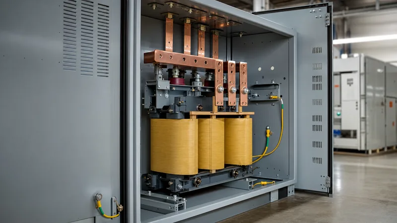
Key takeaways
- A 480 to 240 transformer steps down standard industrial supply voltage by a 2:1 turns ratio to supply motors, manufacturing machinery, and building distribution subpanels.
- Three-phase full-load current on a 240 V secondary is exactly double the line current on a balanced 480 V primary, calculated via I = kVA / (sqrt(3) x V).
- Delta-Delta winding schemes deliver three-wire 240 V three-phase power, whereas a Delta-Wye scheme yields 240Y/139 V, requiring careful load compatibility assessments.
- Standard off-nominal supply fluctuations are compensated using primary full-capacity above-nominal (FCAN) and full-capacity below-nominal (FCBN) de-energised tap changers.
- Installation must comply with NEC Article 450 for overcurrent protection sizing and IEEE C57.12 guidelines for temperature rise and enclosure ventilation.
Quick answer: A 480 to 240 transformer is an electrical distribution transformer designed to step down a nominal 480 V primary service to a 240 V secondary utilisation voltage. Available in single-phase and three-phase designs, it supplies industrial processing machinery, commercial HVAC plant, and motor control centres requiring 240 V or 230 V input.
Industrial utilities across North America and standard international 60 Hz distribution networks deliver primary power at 480 V three-phase. However, an extensive portion of legacy and imported plant machinery, resistive process heating, commercial kitchen equipment, and small motor loads operate at 240 V. Deploying a dedicated step down transformer 480 to 240 provides isolation, mitigates network harmonics, eliminates common-mode electrical noise, and matches utilisation equipment ratings without requiring costly service rebuilds. Selecting the proper unit demands careful evaluation of winding topology, fault current levels, impedance ratings, and thermal enclosure designs.
Understanding Three Phase 480 to 240 V Voltage Conversion
Converting three phase 480 V supply to 240 V entails establishing an electromagnetic link across primary and secondary windings governed by Faraday's law of induction. In a balanced system, the transformation ratio matches the nominal winding turns ratio of 2:1. When designing or procuring a 480 to 240 transformer 3 phase unit, electrical engineers must differentiate between line-to-line (phase-to-phase) voltage and line-to-neutral (phase-to-neutral) potential.
A three-phase 480 V supply is typically delivered from a 480Y/277 V utility service, offering 480 V across phases and 277 V to neutral. When stepping this voltage down to 240 V, the configuration of the secondary determines the available phase and neutral voltages. Supplying three-phase 240 V motor loads requires a 240 V phase-to-phase output. If single-phase 120 V loads must also be served from the same unit, engineers frequently implement a centre-tapped secondary winding (known as a 240/120 V high-leg delta). In this arrangement, two phases provide 120 V to neutral, while the third 'high leg' sits at 208 V relative to neutral. Misidentifying this output profile risks fatal overvoltage damage to connected single-phase 120 V equipment.
Winding Configurations for a 480V 3 Phase Transformer
Winding connections in a 480v 3 phase transformer dictate system grounding, fault path propagation, and harmonic suppression throughout the downstream distribution network. Most industrial step-down applications employ one of two principal vector configurations: Delta-Delta (Dd) or Delta-Wye (Dy).
A Delta primary isolates the secondary distribution network from zero-sequence harmonic currents generated upstream. As detailed in our engineering guide to delta-wye transformers, a Delta-Wye configuration creates an artificial neutral on the secondary. However, establishing a secondary line-to-line voltage of 240 V in a Wye winding yields a line-to-neutral potential of 138.5 V (240 V / 1.732), which is incompatible with standard 120 V single-phase loads. Therefore, when 240 V three-phase power and 120 V single-phase utility power are required from a single transformer, industrial facilities often specify a Delta-Delta transformer with a centre tap on one winding, or install a separate 480 to 208Y/120 V transformer for general-purpose lighting and receptacles.
- Delta-Delta (480 V Delta to 240 V Delta): Ideal for dedicated three-phase motor loads, variable frequency drives (VFDs), and heavy industrial equipment without neutral requirements.
- Delta-Delta with Centre-Tap Ground: Delivers 240 V three-phase across lines, with 120 V available from phase A or C to the grounded centre tap on the B-phase winding.
- Delta-Wye (480 V Delta to 240Y/139 V): Used primarily when balanced line-to-line 240 V loads require a solidly grounded secondary neutral point for ground-fault sensing, though 139 V cannot serve conventional 120 V equipment.
Full Load Current Ratings for a 480V to 240V Step Down Transformer
Accurate current calculations for a 480v to 240v step down transformer ensure appropriate sizing of primary and secondary conductors, circuit breakers, and protective relays. For three-phase units, full load line current is inversely proportional to system voltage, meaning secondary current is precisely double the primary current under identical power factors and balanced conditions.
The three-phase current formula is expressed as:
I = kVA x 1,000 / (V_line x 1.732)
Where I is current in amperes, kVA represents the transformer rating, and V_line is the phase-to-phase operating voltage. Consult our transformer sizing calculator guide for custom capacity assessments. The table below outlines standard electrical design values across common commercial kVA sizes according to IEEE C57.12.01 standards:
| Capacity Rating (kVA) | Primary Current at 480 V (A) | Secondary Current at 240 V (A) | Typical Impedance (%Z) | Minimum DOE Efficiency (%) |
|---|---|---|---|---|
| 15 | 18.0 | 36.1 | 3.0 - 4.5 | 97.89 |
| 30 | 36.1 | 72.2 | 3.5 - 5.0 | 98.23 |
| 45 | 54.1 | 108.3 | 3.5 - 5.0 | 98.40 |
| 75 | 90.2 | 180.4 | 4.0 - 5.5 | 98.60 |
| 112.5 | 135.3 | 270.6 | 4.0 - 5.5 | 98.74 |
| 150 | 180.4 | 360.8 | 4.5 - 6.0 | 98.83 |
| 225 | 270.6 | 541.3 | 4.5 - 6.0 | 98.94 |
| 300 | 360.8 | 721.7 | 5.0 - 6.5 | 99.02 |
| 500 | 601.4 | 1202.8 | 5.0 - 6.5 | 99.14 |
Operating 230V Equipment: 480V to 230V 3 Phase Transformer Tap Settings
Specifying a 480v to 230v 3 phase transformer is often unnecessary when standard 480 to 240 V units feature primary de-energised tap changers. Motors and industrial drives nominally rated at 230 V operate reliably within a plus or minus 10% voltage tolerance band (207 V to 253 V) under NEMA MG-1 and IEC 60034-1 specifications. Supplying a nominal 240 V terminal potential falls well within this allowable range.
However, if long cable runs cause severe voltage drop or the grid supply delivers elevated voltage (e.g., 495 V instead of 480 V), secondary voltage can rise beyond 250 V, risking motor insulation breakdown or control circuit tripping. Standard general-purpose distribution transformers incorporate Full Capacity Below Normal (FCBN) and Full Capacity Above Normal (FCAN) tap arrangements on the primary winding. Typically configured as two 2.5% taps above and two 2.5% taps below normal (+2 x 2.5%, -2 x 2.5%), these taps permit adjustment of the transformation ratio without reducing continuous power ratings. Connecting to a +5% tap reduces secondary output voltage from 240 V to approximately 228 V under 480 V input, providing a precision fit for strict 230 V equipment loads.
Step-by-Step Installation and Wiring Procedure
Installing and energising a step-down transformer requires strict adherence to safety standards, including the National Electrical Code (NEC / NFPA 70) and IEEE guidelines. The following sequential commissioning procedure ensures safe and reliable integration:
- De-energise and lock out upstream supply: Isolate the 480 V primary feeder at the main switchboard, verify zero energy with a calibrated multimeter, and apply appropriate lock-out/tag-out (LOTO) padlocks.
- Position and secure the enclosure: Mount the transformer on an engineered vibration-isolation pad or structural housekeeping slab, maintaining minimum clearances (typically 150 mm to 300 mm from walls) to facilitate airflow through cooling louvres.
- Establish the equipment and system grounding: Bond the transformer enclosure to the primary grounding conductor. If establishing a derived neutral, install a bonding jumper to the building grounding electrode conductor in compliance with NEC Article 250.30.
- Adjust primary taps to line conditions: Measure ambient input line voltage and set internal tap links to the corresponding nominal, FCAN, or FCBN terminals prior to terminating feeder cables.
- Terminate primary (H1, H2, H3) and secondary (X1, X2, X3) conductors: Strip cables using manufacturer-approved tooling, fit compression lugs, and torque all terminal hardware to prescribed torque ratings using a calibrated torque wrench.
- Perform pre-energisation insulation tests: Conduct insulation resistance testing (megohmmeter at 1,000 V DC for primary, 500 V DC for secondary) between phases and phase-to-ground, ensuring values exceed minimum industry thresholds (typically greater than 100 megohms).
- Energise under no-load conditions: Remove test gear, clear the enclosure, replace all access panels, close the upstream breaker, and measure secondary line-to-line voltages to confirm balanced 240 V output before applying mechanical load.
Dry-Type vs Oil-Immersed Distribution Transformers
Choosing between dry-type and oil-immersed construction for a 480 to 240 V application depends heavily on environmental exposure, fire suppression codes, and indoor versus outdoor siting constraints. The physical construction dictates overall lifespan, maintenance intervals, and acoustic decibel ratings.
For indoor commercial buildings, manufacturing plant mezzanines, and cleanrooms, engineers universally specify dry-type transformers equipped with ventilated NEMA 1 or NEMA 3R enclosures. Modern dry-type units utilise vacuum pressure impregnated (VPI) or cast resin insulation systems rated for Class 220 (H) thermal endurance with temperature rises limited to 80°C, 115°C, or 150°C. They contain no combustible fluids, emit zero toxic gases during fault arcs, and avoid the requirement for concrete containment berms. Conversely, when step-down transformation occurs outdoors at the service entrance or in heavy industrial facilities with corrosive dust, oil-immersed transformers provide superior thermal dissipation, higher basic impulse insulation levels (BIL), and total environmental sealing inside hermetically welded steel tanks.
Next steps: specifying and sourcing
When preparing an inquiry or request for quotation for a 480 to 240 transformer, having clear engineering specifications ensures fast turnaround and accurate manufacturing. Essential parameters include total continuous kVA load, supply frequency (50 Hz or 60 Hz), primary and secondary vector configuration, ambient operating temperatures, winding material (copper or aluminium), and enclosure NEMA/IP ratings. Whether you require standard industrial dry-type units or customised outdoor substation equipment, explore our specialised dry-type transformers and heavy-duty oil-immersed transformers. For bespoke engineering evaluations, submittal drawings, and wholesale manufacturing pricing, submit your project schedule through our transformer quotation portal.
Frequently asked questions
Can I run a 240V three-phase transformer in reverse to step up from 240V to 480V?
Yes, standard isolation transformers can be back-fed in reverse, but doing so alters inrush characteristics and terminal designations. When back-feeding a Delta-Wye unit, the Wye winding becomes the primary, creating an ungrounded or floating neutral condition that can cause dangerous line-to-ground voltages. To avoid protective nuisance tripping and code violations, always verify reverse-feed ratings with the manufacturer.
What is the difference between a 480V to 240V transformer and a 480V to 208Y/120V transformer?
A 480 to 240 V transformer produces 240 V phase-to-phase, which is required for heavy industrial machinery, motors, and commercial cooking gear. A 480 to 208Y/120 V transformer provides 208 V line-to-line and 120 V line-to-neutral, making it the standard choice for general office receptacles, standard computers, and interior architectural lighting.
How do I size overcurrent protection for a 480 to 240 transformer?
Overcurrent protection must comply with NEC Article 450.3. For transformers operating under 1,000 V with primary-only protection, the circuit breaker or fuse is typically sized up to 125% of the primary rated current. If both primary and secondary protection are installed, primary protective devices can be sized up to 250%, provided secondary protection does not exceed 125% of secondary full load current.
Will a 240V secondary damage motors rated for 230V?
No, a nominal 240 V secondary will not harm a 230 V motor under normal operation. Standard electric motors manufactured according to NEMA MG-1 and IEC standards possess an allowable voltage tolerance of plus or minus 10%, meaning a 230 V motor is designed to operate safely between 207 V and 253 V.
Why is there a high leg on some 240V delta transformer secondaries?
A high leg occurs when a 240 V Delta secondary winding is centre-tapped on one phase to provide 120 V line-to-neutral power for convenience circuits. Geometry dictates that the phase opposite the centre tap sits at 208 V (120 V multiplied by the square root of 3) relative to the neutral conductor, requiring clear identification (orange marking) to prevent improper single-phase connections.
Tags: 480 to 240 transformer step down transformer 480 to 240 three phase 480 480 to 240 transformer 3 phase 480v 3 phase transformer


