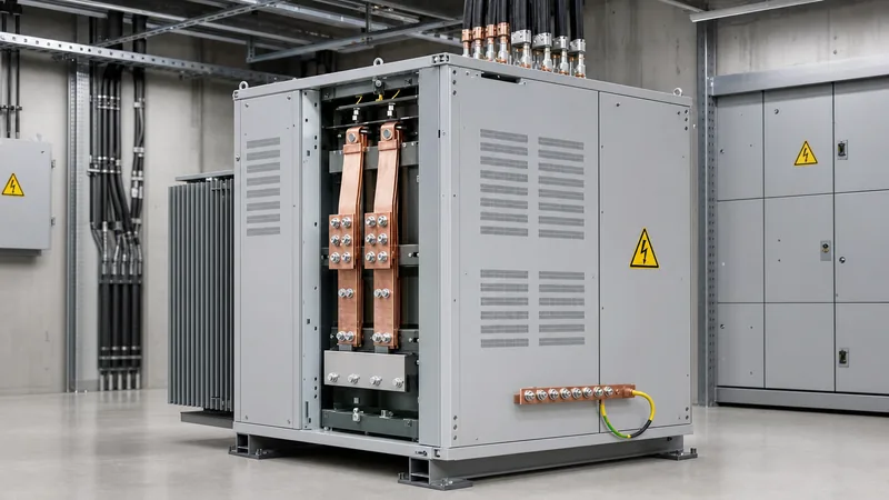
Key takeaways
- A 240 208 transformer adapts 240V 3-phase supplies (commonly delta) to 208Y/120V 4-wire systems required by sensitive commercial and IT equipment.
- The primary winding line current at 240V is calculated as I = kVA × 1000 / (240 × √3), which is roughly 15% lower than the 208V secondary current.
- Delta-wye isolation units establish a brand-new, separately derived neutral point compliant with NEC Article 250.30, eliminating neutral shift hazards.
- Autotransformers or buck-boost arrangements offer lower initial cost and smaller footprints for pure 240V to 208V reduction, but they cannot derive a safe 120V line-to-neutral load.
- Proper specification requires confirming winding materials, sound levels per standard NEMA guidelines, impedance percentage (%Z), and temperature rise ratings (typically 115°C or 150°C over 40°C ambient).
Quick answer: A 240 208 transformer is a dry-type or liquid-filled distribution unit that steps down a 240V three-phase supply to 208V three-phase (most commonly 208Y/120V). It resolves voltage incompatibility between legacy 240V delta networks and modern commercial equipment engineered for 208V operation.
In North American and international industrial facilities, matching facility supply voltage to equipment nameplates is critical for operational life and thermal efficiency. Older light-industrial installations and rural commercial estates frequently feature 240V three-phase delta electrical services. However, contemporary commercial kitchen machinery, computer room air handlers (CRAHs), data centre servers, and CNC machine tools are designed to operate at 208V. Connecting 208V-rated devices directly to an ungrounded or high-leg 240V supply exposes motors and power electronics to excessive overvoltages, premature winding insulation failure, and control board trips. This engineering guide details the operating principles, wiring configurations, sizing rules, and selection criteria for stepping down 240V to 208V.
What Is a 240 208 Transformer and How Does It Operate?
A 240 208 transformer is an electromagnetic voltage converter designed to bridge the voltage gap between a 240V three-phase line and equipment requiring a nominal 208V supply. Electrically, stepping down from 240V to 208V represents an exact transformation ratio of 1.154:1 (or approximately a 13.3% voltage reduction). Under standard electromagnetic induction governed by Faraday's law, primary windings exposed to an alternating magnetic flux induce a proportionally reduced voltage in the secondary coils based on turns ratio.
These units are manufactured either as standard two-winding isolation transformers or as specialised buck-boost autotransformers. In an isolation configuration, the primary and secondary windings remain galvanically separated by high-grade electrical insulation (such as Class 180°C or 220°C high-temperature materials). In contrast, autotransformer designs share a portion of the winding, making them lighter and more compact. Engineers selecting equipment can consult our 3 Phase Transformer Guide for an overarching review of core laminations, efficiency regulations, and cooling classes.
Why Install a Step Down Transformer 240 to 208 3 Phase?
Installing a step down transformer 240 to 208 3 phase prevents severe overvoltage damage to 208V-rated motors, Variable Frequency Drives (VFDs), and precision instruments. When a load designed for 208V ±10% (tolerance band of 187V to 229V) is connected to a nominal 240V service, the applied voltage operates at the absolute maximum limit or exceeds it during utility peak periods. At 240V, the iron core of a 208V electric motor saturates, driving core losses upward by 15% to 30%, which significantly increases thermal stress and causes nuisance tripping of thermal overloads.
Furthermore, many commercial premises possess an existing 240V delta "high-leg" or "stinger leg" service (where one phase measures 208V to neutral while the other two measure 120V to neutral). Attempting to power standard single-phase 120V branch circuits from the high leg causes immediate equipment burnout. Deploying a dedicated step-down isolation unit provides a balanced secondary system with equal line-to-neutral voltages, mitigating the risk of incorrect field connections and ensuring compliance with NFPA 70 (National Electrical Code) Article 450.
Wiring and Vector Configurations: Delta to Wye Conversion
The standard wiring configuration for a 240v to 208v step down transformer is a Delta primary paired with a Wye (Star) secondary, designated as Dyn1 or Dyn11 depending on the phase displacement angle. A 240V Delta primary accepts three ungrounded phase conductors without requiring a neutral conductor. The secondary winding is connected in a Wye configuration to supply 208V line-to-line (Ph-Ph) across terminals X1, X2, and X3, as well as 120V line-to-neutral (Ph-N) between any phase terminal and the neutral point (X0).
Proper secondary grounding is vital for circuit safety and transient mitigation. According to IEEE C57.12.01 and NEC 250.30 standards, the X0 terminal of a separately derived system must be bonded directly to the grounding electrode conductor (GEC) and the equipment grounding conductor (EGC) inside the transformer enclosure or first disconnecting means. Detailed vector diagrams and terminal terminal markings can be examined in our guide on Delta Wye Transformer Diagrams. If your facility requires the reverse operation or alternative stepping, refer to our analysis on 480 to 240 Transformer Guide for comparison.
Step-by-Step Sizing Procedure for 240V to 208V Systems
Sizing a 240 208 transformer accurately requires determining the total connected load, calculating operational currents, and factoring in equipment power factors and motor inrush. Undersized units suffer from excessive core heating and voltage sag during motor starts, while oversized units introduce unnecessary no-load core losses.
- Calculate continuous and non-continuous loads: Sum the steady-state kVA ratings of all connected loads. Add 125% for continuous loads (running uninterrupted for 3 hours or more) as mandated by electrical codes.
- Determine total full-load secondary current: Apply the three-phase formula: I_sec = (Load kVA × 1000) / (208 × √3). For instance, a 30 kVA load draws 83.27 A at 208V.
- Calculate primary input current: Use the primary line voltage to find full-load ampacity: I_pri = (Load kVA × 1000) / (240 × √3). The 30 kVA load draws 72.17 A at 240V.
- Select standard kVA rating: Select the next standard commercial kVA rating that meets or exceeds your calculated kVA demand. Standard ratings include 15, 30, 45, 75, 112.5, 150, 225, and 300 kVA.
- Verify motor inrush requirements: For direct-on-line (DOL) electric motors, confirm the transformer's impedance (%Z, usually between 3.0% and 5.5%) limits voltage dip to within 10% during startup. Engineers can check their load margins using our Transformer Sizing Calculator Guide.
Full-Load Current and Specification Reference Table
The engineering reference table below outlines standard electrical parameters for three-phase 240V Delta to 208Y/120V transformers, including full-load primary and secondary currents alongside typical circuit protection requirements based on standard UL 1561 and NEC Article 450 benchmarks.
| Capacity Rating (kVA) | Primary Current at 240V (A) | Secondary Current at 208V (A) | Typical Impedance (%Z) | Maximum Recommended Primary OCPD (A) | Minimum Secondary Conductor (AWG/kcmil, Cu) |
|---|---|---|---|---|---|
| 15 | 36.1 | 41.6 | 3.0% - 4.5% | 60 | #6 AWG |
| 30 | 72.2 | 83.3 | 3.5% - 5.0% | 100 | #3 AWG |
| 45 | 108.3 | 124.9 | 3.5% - 5.5% | 150 | #1/0 AWG |
| 75 | 180.4 | 208.2 | 4.0% - 5.5% | 250 | 4/0 AWG |
| 112.5 | 270.6 | 312.3 | 4.5% - 5.8% | 400 | 350 kcmil |
| 150 | 360.8 | 416.4 | 4.5% - 6.0% | 500 | 500 kcmil |
| 225 | 541.3 | 624.5 | 5.0% - 6.5% | 800 | 2 × 300 kcmil |
| 300 | 721.7 | 832.7 | 5.0% - 6.5% | 1000 | 2 × 500 kcmil |
Isolation Transformer vs Autotransformer: Evaluating Topologies
Deciding between an isolation transformer and an autotransformer depends entirely on whether your secondary distribution requires an independent neutral and galvanic decoupling. An isolation transformer creates a physically separated secondary circuit. This isolates harmonics, absorbs transient line spikes, and generates a clean 120V line-to-neutral leg via its secondary wye centre point.
Conversely, a buck-boost autotransformer interconnected in a 3-phase configuration utilizes shared windings to reduce the line-to-line potential from 240V to 208V. Because it transforms only a fraction of the power (the 32V differential), the autotransformer physical footprint is smaller, cost is substantially lower, and electrical efficiency often exceeds 98.5%. However, an autotransformer does not isolate the load from upstream ground faults, nor can it create a usable 120V single-phase neutral from an ungrounded or delta 240V supply. For facilities requiring heavy-duty floor-mounted enclosures with integral galvanic safety, reviewing commercial dry-type transformers or outdoor pad-mounted transformers is recommended.
Next steps: specifying and sourcing
When preparing an RFQ for a 240 208 transformer, verify key project parameters with your engineering team: load capacity in kVA, enclosure protection grade (e.g., NEMA 1/3R or standard ingress protection ratings), winding material (copper vs aluminium), sound level thresholds, and BIL (Basic Impulse Level) ratings. Contact our engineering team for technical datasheets, dimension drawings, and factory performance test reports, or submit your specific load details directly through our transformer quotation page. You can also explore our full range of certified industrial systems across our dry-type transformer line.
Frequently asked questions
Can I run a 208V machine directly on a 240V supply without a transformer?
No, running 208V machinery on 240V leads to severe thermal saturation and insulation breakdown. While some equipment nameplates read 208-240V, equipment rated exclusively for 208V will overheat because 240V exceeds the standard ±10% voltage tolerance.
What is the primary difference between an isolation transformer and an autotransformer for 240V to 208V?
An isolation transformer provides galvanic separation and can establish a stable 120V neutral point via a secondary wye winding. An autotransformer physically connects primary and secondary windings, providing an economical voltage drop but without ground isolation or a 120V neutral.
Can a 240 208 transformer be back-fed to step up from 208V to 240V?
Most industrial dry-type transformers can be back-fed, but doing so increases initial inrush current by up to 15 times normal levels. When back-feeding a Wye-Delta arrangement, primary grounding and overcurrent protective devices must be specifically calculated per NEC Article 450.
How do you calculate breaker size for a 240 to 208 transformer?
Primary overcurrent protection is typically sized at 125% of the rated full-load primary current under NEC 450.3(B). For instance, a 45 kVA transformer drawing 108.3A at 240V requires a breaker sized between 125A and 150A depending on inrush characteristics.
Does a 240V to 208V 3-phase transformer produce 120V single-phase power?
Yes, if the transformer features a Delta primary and a 208Y/120V Wye secondary. Line-to-line voltage will measure 208V across any two phases, while line-to-neutral voltage will deliver 120V across any single phase and the grounded X0 terminal.
Tags: 240 208 transformer step down transformer 240 to 208 3 phase 240v to 208v step down transformer dry type transformer transformer sizing


