Key takeaways
- A three phase step up transformer raises line-to-line alternating voltage between primary and secondary windings via electromagnetic induction while conserving total apparent power minus internal core and copper losses.
- Industrial low-voltage conversions commonly step up 208Y/120 V commercial supply grids to 480 V delta or 480Y/277 V to power heavy three-phase industrial machinery and motor control centres.
- Vector groups such as Dyn11 or YNd1 provide a 30-degree electrical phase displacement that suppresses third-harmonic flux and establishes a stable secondary ground reference.
- Reverse-feeding a standard step-down unit incurs elevated inrush currents up to 10 to 12 times full-load current and can lead to secondary under-voltage due to uncompensated internal turns-ratio regulation.
- Transformer sizing requires multiplying continuous loads by 125 percent under NEC Article 450 or IEC 60076 thermal guidelines to avoid thermal derating and nuisance breaker tripping.
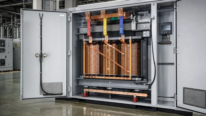
Quick answer: A three phase step up transformer is an electromagnetic induction device designed to increase three-phase alternating current (AC) voltage from a lower supply level to a higher distribution or utilisation level. Operating across synchronized 120-degree phase displacements, it delivers balanced high-voltage power to heavy industrial machinery, medium-voltage distribution networks, and grid interconnections while preserving system frequency.
In commercial, manufacturing, and utility power distribution, voltage mismatch is a common engineering challenge. Modern facilities routinely receive low-voltage service feeds—such as 208Y/120 V or 240 V three-phase—yet require 480 V, 600 V, or medium-voltage power to operate process heaters, large induction motors, and variable frequency drives (VFDs). Stepping up voltage reduces line current proportionally, which lowers conductor cross-sectional requirements and curtails $I^2R$ resistive cable losses over extended runs. For a comprehensive overview of construction methodologies and operational physics across all three-phase equipment, refer to our 3 Phase Transformer Guide.
Operating Principles and Vector Configurations
A three phase step up transformer operates on Faraday's law of electromagnetic induction, transferring power between magnetically coupled primary and secondary windings where the secondary winding has a higher number of turns ($N_s > N_p$). The fundamental phase-to-phase voltage ratio matches the effective winding turns ratio, governed by the formula $V_s / V_p = N_s / N_p$, assuming negligible leakage impedance under no-load conditions.
Three-phase magnetic cores are typically built using high-permeability, cold-rolled grain-oriented (CRGO) silicon steel configured in three-limb or five-limb geometries. The arrangement of the primary and secondary winding connections determines the transformer's vector group, which dictates phase displacement and harmonic mitigation. The most prevalent configurations for industrial step-up duties include:
- Delta-Wye (Dyn11 or Dyn1): The primary winding is connected in delta ($\Delta$), which traps third-harmonic (180 Hz) zero-sequence currents within the closed loop, preventing harmonic injection upstream into the grid. The secondary winding is connected in wye (Y), establishing a clean, earthed neutral terminal that provides both line-to-line voltage (such as 480 V) and line-to-neutral voltage (such as 277 V).
- Wye-Delta (YNd11 or YNd1): Frequently applied in utility generation where the neutral point of a generator requires direct system earthing, stepping up to a delta transmission or distribution interface. Detailed wiring configurations for these geometries are examined in our technical breakdown of the Delta Wye Transformer Diagram.
- Wye-Wye (YNy0): Provides a common neutral connection throughout both systems, but requires a tertiary delta winding or a five-limb core to mitigate third-harmonic flux instability and avoid excessive tank heating under unbalanced loads.
Low-Voltage Conversions: The 120V to 480V Step Up Transformer
Specifying a 120v to 480v step up transformer requires distinguishing between line-to-neutral and line-to-phase electrical architecture. In standard North American commercial facilities, a nominal 120 V circuit is derived as the line-to-neutral potential of a three-phase 208Y/120 V wye electrical service. Therefore, an engineer seeking a 120 to 480 step up transformer is almost universally sourcing a three-phase 208Y/120 V primary to 480Y/277 V (or 480 V Delta) secondary unit.
True 120 V line-to-line three-phase systems are virtually non-existent in utility distribution networks due to excessive conductor sizing constraints. If equipment specifies 120 V input stepping up to 480 V three-phase, system designers must clarify whether the supply consists of three individual 120 V single-phase legs referenced to ground, or if the source is a standard 208 V phase-to-phase network. For specific line calculations and impedance considerations regarding this transition, consult our dedicated 208 to 480 Transformer Guide.
When stepping up from 208 V (with 120 V to neutral) to 480 V, the step-up ratio is approximately 1:2.307. Because secondary current is inversely proportional to voltage ($I_s = I_p \times [V_p / V_s]$), primary feeders must carry 2.3 times the secondary full-load current. Primary switchgear, busbars, and protection devices must be rated accordingly to handle this elevated continuous amperage without exceeding allowable thermal limits under standard IEC 60076-2 or IEEE C57.12.00 operating criteria.
Factory-Built Step-Up vs Reverse-Feeding Step-Down Units
Reverse-feeding a standard step-down transformer to function as a step-up transformer is permitted under specific conditions, but it introduces significant operational and safety compromises. Electrical distribution transformers engineered specifically for step-up applications feature compensation winding adjustments, optimised magnetic core geometries, and tap changers located on the designated primary winding.
When a standard step-down transformer is reverse-energised (applying voltage to the low-voltage secondary terminals):
- Turns Ratio Losses: Standard step-down units feature a 2.5% to 5% turns-ratio compensation built into the low-voltage winding to offset internal voltage drop under full load. In reverse, this internal compensation compounds the voltage drop, delivering an output voltage 3% to 5% below nominal ratings under full load.
- Severe Inrush Current: Low-voltage windings wound closest to the core possess lower leakage reactance. Energising this winding creates severe magnetising inrush currents up to 12 to 15 times the full-load current (FLC), frequently causing instantaneous trips on upstream protective circuit breakers.
- Tap Changer Inversion: Taps designed on the high-voltage winding of a step-down transformer will function backwards when reverse-fed, causing off-nominal voltage regulation errors if technicians are not properly trained.
- Earthing Complications: Reverse-feeding a Delta-Wye step-down unit forces the primary supply into a wye configuration and the secondary output into a delta configuration. This eliminates the neutral point on the output side, preventing line-to-neutral power delivery unless an external neutral grounding transformer or zig-zag grounding bank is installed.
Technical Specifications and Sizing Metrics
Selecting an industrial step-up transformer requires evaluating continuous kVA capacity, winding materials, impedance percentage (%Z), insulation temperature class, and efficiency standards such as DOE 2016 (10 CFR Part 431) or EU EcoDesign EN 50588-1. Sizing calculations rely on the fundamental three-phase apparent power formula:
$$S = \sqrt{3} \times V_L \times I_L$$
Where $S$ is apparent power in volt-amperes (VA), $V_L$ is line-to-line voltage in volts (V), and $I_L$ is line current in amperes (A). The table below outlines mechanical and electrical specifications across typical low-voltage step-up transformer sizes engineered to step up a 208 V supply to 480 V at 60 Hz:
| Rating (kVA) | Primary Volts (V) | Secondary Volts (V) | Primary FLC (A) | Secondary FLC (A) | Typical Impedance (%Z) | Full-Load Efficiency (%) |
|---|---|---|---|---|---|---|
| 45 | 208Y / 120 | 480Y / 277 | 124.9 | 54.1 | 3.5 - 4.5 | 98.40 |
| 75 | 208Y / 120 | 480Y / 277 | 208.2 | 90.2 | 4.0 - 5.0 | 98.60 |
| 112.5 | 208Y / 120 | 480Y / 277 | 312.3 | 135.3 | 4.5 - 5.5 | 98.74 |
| 150 | 208Y / 120 | 480Y / 277 | 416.4 | 180.4 | 4.5 - 5.5 | 98.83 |
| 300 | 208Y / 120 | 480Y / 277 | 832.7 | 360.8 | 5.0 - 6.0 | 99.02 |
| 500 | 208Y / 120 | 480Y / 277 | 1387.9 | 601.4 | 5.5 - 6.5 | 99.15 |
For specialized installations requiring bespoke load-profiling calculations, engineers can cross-reference our interactive Transformer Sizing Calculator Guide to verify thermal margins under nonlinear harmonic load profiles (K-factor ratings).
Step-by-Step Selection and Sizing Procedure
Correctly sizing and specifying a three phase step up transformer requires an orderly engineering evaluation to guarantee voltage stability, code compliance, and sufficient thermal headroom. Follow this six-step procedure:
- Calculate Total Connected Load: Aggregate all connected equipment loads in amperes or kilowatts. Convert all kW values to kVA by dividing the active power by the operational load power factor ($\text{kVA} = \text{kW} / \text{PF}$, typically assuming 0.85 PF for mixed industrial motor loads).
- Apply Continuous Load Factors: Under standards such as NFPA 70 (NEC Article 450) and IEC 60076, loads operating continuously for three hours or longer must be factored at 125% of their nominal continuous rating: $\text{kVA}_{\text{required}} = (\text{Continuous kVA} \times 1.25) + \text{Non-Continuous kVA}$.
- Select Standard Nameplate Rating: Round the calculated requirement up to the next commercially standard kVA capacity (e.g., 45, 75, 112.5, 150, 225, 300, 500 kVA). Never size a transformer below calculated continuous demand.
- Determine Primary and Secondary Current: Compute full-load operational currents on both sides of the unit using $I = S / (\sqrt{3} \times V_L)$ to establish breaker ratings, cable cross-sections, and conduit fill requirements.
- Assess Inrush Current and Upstream Coordination: Verify that upstream protective devices can clear typical magnetising inrush (10 to 12 times $I_{FLC}$ for 0.1 seconds) without nuisance tripping, selecting circuit breakers equipped with adjustable short-time pickup ($I^2t$) settings.
- Verify Environmental and Insulation Ratings: Determine whether the application demands a ventilated dry type transformer (Class 220°C insulation with 150°C, 115°C, or 80°C rise) for indoor switchgear rooms, or an environmentally sealed oil immersed transformer utilizing mineral oil or high-fire-point ester dielectric fluid for outdoor or medium-voltage grid ties.
Protection, Grounding, and Code Compliance
Proper protection and grounding of a three phase step up transformer ensure system longevity and personnel safety under short-circuit and ground-fault conditions. Article 450 of the National Electrical Code (NEC) and IEC 60076 govern overcurrent protection limits, specifying that primary overcurrent protective devices (OCPDs) without secondary protection must generally not exceed 125% of the transformer's rated primary current for units rated over 9 A.
When secondary protection is provided, the primary breaker setting can be increased up to 250% (under NEC Table 450.3(B)), provided the secondary OCPD does not exceed 125% of the rated secondary full-load current. This dual-protection architecture prevents high magnetising inrush current from opening the primary feeder while maintaining thermal overload protection for the windings.
System grounding requires particular attention on the secondary side of a step-up transformer. If the unit features a wye secondary winding, it functions as a separately derived system. A system bonding jumper must be installed between the secondary neutral terminal ($X_0$) and the equipment grounding conductor (EGC), routed to an approved grounding electrode conductor (GEC). Solidly grounding the secondary neutral stabilizes phase voltages relative to ground and ensures a reliable, low-impedance path to trip protective breakers during line-to-ground faults.
Next steps: specifying and sourcing
When preparing an inquiry or request for quotation (RFQ) for a custom or standard three phase step up transformer, ensure your engineering documentation clearly details primary and secondary operating voltages, total kVA demand, vector configuration, winding material (copper or aluminium), and system frequency (50 Hz or 60 Hz). Include any harmonic mitigation requirements (K-factor) and special environmental parameters, such as outdoor NEMA 3R/4X or IP54 enclosures. Explore our specialized dry-type transformers, heavy-duty power transformers, and complete transformer substations to match your system design. To submit your electrical single-line diagrams or request factory-direct quotations, contact our application engineering department at request a quotation or visit our contact page.
Frequently asked questions
Can a step-down transformer be reverse-fed as a three phase step up transformer?
Yes, a step-down transformer can physically be reverse-fed, but it is not optimal. Reverse-feeding induces severe magnetising inrush currents up to 15 times nominal current, causes a 3% to 5% secondary voltage reduction due to built-in turns-ratio compensation, and limits grounding options if converting from a delta primary to a wye secondary.
What is the difference between a 120v to 480v step up transformer and a 208v to 480v unit?
They generally describe the exact same three-phase equipment. In standard commercial three-phase distribution, 120 V represents the line-to-neutral voltage of a 208Y/120 V wye service. Stepping up to 480 V three-phase requires using the 208 V line-to-line supply to generate a 480 V phase-to-phase output.
What vector group is most common for a three phase step up transformer?
The Dyn11 vector group is the most widely specified configuration for low-to-medium voltage step-up applications. The delta primary suppresses third harmonics and eliminates the need for an upstream neutral conductor, while the wye secondary establishes a stable neutral terminal that can be solidly grounded.
How do you calculate the full load current for a three phase step up transformer?
Full load current is calculated using the formula I = kVA / (V * 1.732) * 1000, where V is the line-to-line voltage. For example, a 150 kVA transformer operating at 480 V secondary produces 150,000 / (480 * 1.732) = 180.4 amperes of full load secondary current.
Why are three phase step up transformers used in renewable energy systems?
Three phase step up transformers are essential in renewable installations to elevate the low AC output voltages of solar or battery inverters (typically 400 V to 800 V) to medium-voltage collector levels (such as 13.8 kV, 22 kV, or 34.5 kV). This high-voltage step minimizes cable losses over long distances to the utility substation.
Does a three phase step up transformer change the electrical frequency?
No, a passive transformer cannot change system frequency. A 60 Hz input will yield a 60 Hz output, and a 50 Hz input will yield a 50 Hz output. Changing electrical frequency requires an active power conversion system, such as a variable frequency drive or rotary frequency converter.
Tags: three phase step up transformer 120v to 480v step up transformer 120 to 480 step up transformer step up transformer sizing transformer vector groups


