Key takeaways
- Three-phase panelboard capacity is √3 × V × I; a 225 A panel carries about 81 kVA at 208Y/120 V and about 187 kVA at 480Y/277 V.
- Breaker spaces rotate through phases A, B and C down each side, so a three-pole breaker occupies three adjacent spaces and connects to all three phases.
- In a 240/120 V high-leg delta panel, NEC 408.3(E) requires the high leg on the B phase and NEC 110.15 requires orange marking, since it measures about 208 V to neutral.
- Neutral current in an unbalanced wye panel with linear loads is √(Ia² + Ib² + Ic² − IaIb − IbIc − IcIa), so 100, 80 and 60 A loads give about 35 A.
- Panelboards are listed to UL 67 in the US and typically range to 1,200 A, while larger services move to UL 891 switchboards or IEC 61439 assemblies.
Quick answer: A 3 phase panel is a panelboard with three phase busbars (A, B and C), usually plus a neutral and ground bar, that distributes three-phase power to single-, two- and three-pole breakers. Common US systems are 208Y/120 V and 480Y/277 V. Capacity is kVA = √3 × V × I / 1000, so a 225 A panel at 208 V supplies about 81 kVA.
Commercial buildings, workshops, farms and factories run on three-phase power because it delivers more power per conductor and starts motors without capacitors or special windings. The 3 phase panel is where that supply is divided into lighting circuits, receptacle circuits and motor feeders.
This guide is for electrical designers, contractors and facility engineers working with commercial and industrial panels. It explains three-phase panel voltages, how the bus and breakers are laid out, how to read a 3 phase panel wiring diagram, how to size a panel from transformer kVA, how to calculate neutral current, and where panelboards end and switchboards begin. Work on energized equipment must follow NFPA 70E and local code and be done by qualified persons.
What Is a 3 Phase Panel?
A three phase electrical panel is a panelboard that receives three ungrounded phase conductors, normally with a neutral, and distributes them through three busbars to branch and feeder breakers. It may be a 3 phase panel with main breaker, used as service equipment or a building main, or a main lug only panel fed from an upstream switchboard.
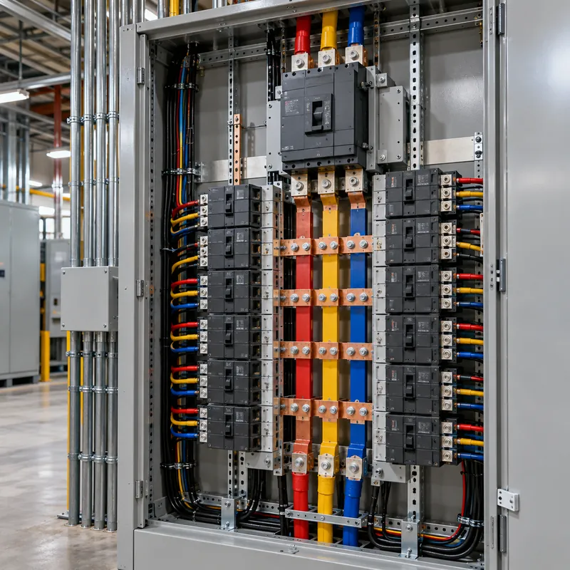
Inside, the bus assembly has three phase bars plus an isolated neutral bar and a ground bar. Breakers connect as follows:
- Single-pole breakers connect one phase to a load returning on the neutral, giving 120 V or 277 V circuits.
- Two-pole breakers connect two phases, giving 208 V or 480 V single-phase circuits.
- Three-pole breakers connect all three phases for three-phase loads such as motors, rooftop units and transformers.
In a four-wire wye system, all three phases are at equal voltage to neutral, which is ideal for lighting and receptacle loads spread across phases; the configuration is explained in 3 phase 4 wire systems.
A 3 phase power panel at service level is called a three phase service panel. A downstream one feeding a floor or a department is a distribution panel. An industrial breaker box in a plant may be a panelboard, a power distribution board or part of a motor control center, depending on what it feeds; see the power distribution board guide.
Common 3 Phase Panel Voltages
| System | Line-to-line | Line-to-neutral | Typical use |
|---|---|---|---|
| 208Y/120 V, 4-wire | 208 V | 120 V | Offices, retail, schools, apartments in the US |
| 480Y/277 V, 4-wire | 480 V | 277 V | Larger commercial, industrial, HVAC, 277 V lighting |
| 240/120 V high-leg delta, 4-wire | 240 V | 120 V on A and C, about 208 V on B | Older commercial and rural services with motors |
| 240 V delta, 3-wire | 240 V | None | Motor-only loads |
| 600Y/347 V, 4-wire | 600 V | 347 V | Commercial and industrial in Canada |
| 400/230 V, 4-wire | 400 V | 230 V | IEC markets: Europe, Asia, Middle East, Africa |
A 240 volt 3 phase panel is usually either a high-leg delta or a corner- or ungrounded delta. In the high-leg delta, the B phase measures about 208 V to neutral and must never feed 120 V loads. NEC 408.3(E) requires the high leg to be the B phase in panelboards, and NEC 110.15 requires it to be marked orange. The transformer side of this system is covered in 3 phase high leg delta transformers.
For most new commercial buildings the choice is between 208Y/120 V for smaller loads and 480Y/277 V with step-down transformers to 208Y/120 V for receptacles; see 277/480 V three-phase systems and 208 V 3 phase power.
3 Phase Panel Wiring Diagram Explained
A 3 phase panel wiring diagram, or three phase panel wiring schematic, shows how incoming conductors land and how circuits are distributed. In a typical 42-circuit panelboard, circuits are numbered odd down the left side and even down the right, and each horizontal row of two circuits is on one phase:
- Circuits 1 and 2 on phase A
- Circuits 3 and 4 on phase B
- Circuits 5 and 6 on phase C
- Circuits 7 and 8 back on phase A, and so on
A three-pole breaker in positions 1-3-5 therefore connects to A, B and C. A two-pole breaker in positions 2-4 connects to A and B.
Reading a 3 phase breaker wiring diagram, the typical sequence of connections is:
- Incoming phase conductors to the main breaker line terminals or main lugs, in A-B-C order left to right.
- Incoming neutral to the isolated neutral bar.
- Incoming equipment grounding conductor to the ground bar, bonded to the enclosure.
- At service equipment only, main bonding jumper between neutral and ground.
- Branch phase conductors to breaker load terminals, neutrals to the neutral bar, grounds to the ground bar.
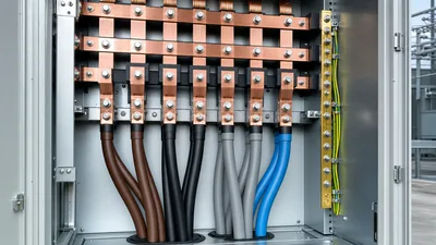
Phase color codes help keep this readable. Common US practice is black, red and blue for 208Y/120 V and brown, orange and yellow for 480Y/277 V, with white or gray neutral and green ground, although the NEC mandates only neutral, ground and high-leg identification. IEC 60445 uses brown, black and gray for L1–L3, blue for neutral and green-yellow for protective earth. See the color code for 3 phase power.
Phase rotation must be checked at the panel before connecting motors, because swapping two phases reverses rotation.
How Do You Size a 3 Phase Electrical Panel?
The basic relationship is I = kVA × 1000 / (√3 × V), or in reverse kVA = √3 × V × I / 1000.
| Panel rating | kVA at 208 V | kVA at 400 V | kVA at 480 V |
|---|---|---|---|
| 100 A | 36 | 69 | 83 |
| 225 A | 81 | 156 | 187 |
| 400 A | 144 | 277 | 333 |
| 600 A | 216 | 416 | 499 |
| 800 A | 288 | 554 | 665 |
| 1,200 A | 432 | 831 | 998 |
Worked example 1, panel fed from a transformer: a 75 kVA, 480 V delta to 208Y/120 V dry-type transformer has secondary full-load current 75,000 / (1.732 × 208) ≈ 208 A. NEC 450.3(B) permits secondary protection up to 125% (260 A, with rounding to the next standard size), but a 225 A main breaker is a common choice because it protects a 225 A panel bus and still carries the 208 A full-load current.
Worked example 2, panel from load: a schedule shows 54 kVA of connected load, with calculated demand of 46 kVA after NEC Article 220 demand factors. At 208 V: 46,000 / (1.732 × 208) ≈ 128 A. With 25% growth, 160 A, so a 225 A panel. The same demand at 480 V is only about 55 A.
Continuous loads must be included at 125% unless the assembly is listed for 100% operation. Breaker interrupting ratings must match the available fault current at the panel. Building up the load list is covered in the panel schedule guide.
Phase Balancing and Neutral Current
Single-phase loads on a three-phase panel rarely balance perfectly. Imbalance raises current on the most loaded phase, increases neutral current and causes voltage unbalance that heats three-phase motors.
For a four-wire wye panel with linear loads at similar power factor, neutral current is:
I_N = √(Ia² + Ib² + Ic² − Ia·Ib − Ib·Ic − Ic·Ia)
Example: phase currents of 100, 80 and 60 A:
I_N = √(10,000 + 6,400 + 3,600 − 8,000 − 4,800 − 6,000) = √1,200 ≈ 34.6 A
Moving 20 A of single-phase load from phase A to phase C gives 80, 80 and 80 A and a theoretical neutral current of zero.
Non-linear loads change this. Single-phase power supplies in computers, LED drivers and EV chargers produce third-harmonic currents that add in the neutral instead of cancelling. In panels serving mostly electronic loads, neutral current can exceed phase current, so designers specify 200% rated neutrals and treat the neutral as a current-carrying conductor for ampacity adjustment under NEC 310.15(E). Upstream transformers may need K-factor ratings.
Good practice for balancing:
- Distribute single-phase loads evenly by calculated VA, not by circuit count.
- Keep phase loads within about 10–15% of each other.
- Recheck after tenant changes, and measure actual phase currents during peak hours.
- Where motors are fed, keep voltage unbalance below 1–2%; NEMA MG 1 derates motors above 1%.
Commercial Electrical Panels: Panelboards, Switchboards and Power Distros
Commercial electrical panel equipment falls into several classes by size and construction:
- Lighting and appliance panelboards (UL 67), typically 100–400 A, 208Y/120 or 480Y/277 V, with bolt-on breakers. The common commercial breaker panel or commercial breaker box.
- Distribution (power) panelboards, up to about 1,200 A, with MCCB feeders to other panels, motors and transformers.
- Switchboards (UL 891) for services from about 400 A to 6,000 A, with metering, ACB or MCCB mains and group-mounted feeders; see switchboard vs panelboard.
- IEC 61439 LV switchboards in IEC markets, with fixed or withdrawable functional units and defined forms of internal separation; see the LV switchboard engineering guide.
- Motor control centers for groups of motor starters and drives.
- Portable 3 phase power distros for events, film sets and construction: rugged boxes with single-pole cam-type or pin-and-sleeve inputs, distributing to outlets and branch breakers, covered in the temporary power distribution guide.
A 3 phase panel box in an industrial plant often needs an enclosure beyond NEMA 1: NEMA 12 for dust and dripping oil, NEMA 4X for washdown or corrosive areas. A power distribution box for 3 phase outdoor use typically needs NEMA 3R minimum.
Selecting between a large panelboard and a switchboard depends on ampacity, fault level, need for metering and future expansion; above roughly 800–1,200 A or where withdrawable breakers are wanted, switchboards or switchgear become the practical choice.
Next Steps: Specifying and Sourcing 3 Phase Distribution Equipment
MARS manufactures three-phase distribution equipment for commercial, industrial and utility projects: IEC 61439 LV switchboards in GGD fixed and GCS and MNS withdrawable designs, KYN28 metal-clad MV switchgear, SF6 ring main units, and the oil-immersed and dry-type distribution transformers and compact substations that feed them, in 50 and 60 Hz versions to IEC, ANSI/IEEE or GB requirements.
For a three-phase board or panel RFQ, specify:
- System voltage and configuration (for example 400/230 V TN-S, 480Y/277 V or 208Y/120 V)
- Main bus rating, neutral rating (100% or 200%) and short-circuit withstand
- Incoming device and outgoing feeder schedule with breaker type and ratings
- Enclosure rating, form of separation, cable entry and space limits
- Metering, protection relays and communication protocols
Size the upstream transformer with the transformer sizing calculator, browse HV and LV switchgear, and send your single-line diagram and panel schedules through the quote request page. Typical lead time is 25–45 days with routine tests on every unit.
Frequently asked questions
What is a 3 phase panel used for?
A 3 phase panel distributes three-phase power in commercial and industrial buildings. It feeds three-phase loads such as motors, HVAC units and transformers through three-pole breakers, and also supplies single-phase lighting and receptacle circuits by connecting single-pole breakers between one phase and neutral, spread across the three phases.
How many kVA can a 200 amp 3 phase panel supply?
Use kVA = √3 × V × I / 1000. At 208 V, a 200 A three-phase panel supplies about 72 kVA. At 480 V it supplies about 166 kVA, and at 400 V about 139 kVA. Continuous loads are limited to 80 percent of the breaker rating unless the equipment is listed for 100 percent operation.
How do you wire a 3 phase breaker panel?
Phase conductors land on the main breaker or lugs in A-B-C order, the neutral on the isolated neutral bar and the ground on the ground bar, with the neutral-to-ground bond only at service equipment. Branch breakers attach to the busbars, which rotate through phases A, B and C. This work must be done by qualified electricians following NFPA 70E and local code.
What is the difference between a 3 phase and single phase panel?
A single-phase panel has two hot busbars and supplies 120 V and 240 V circuits. A three-phase panel has three phase busbars and supplies three-phase loads plus 120 V or 277 V single-phase circuits and 208 V or 480 V two-pole circuits. Three-phase panels deliver more power for the same current.
Why is the high leg on the B phase in a 240 V delta panel?
In a 240/120 V high-leg delta system, one phase measures about 208 V to neutral. NEC 408.3(E) requires it to be connected to the B phase position in panelboards, and NEC 110.15 requires orange marking, so electricians can identify it and avoid connecting 120 V loads to it.
Can a 3 phase panel be used for single phase loads?
Yes. Single-pole breakers supply 120 V or 277 V loads between one phase and neutral, and two-pole breakers supply 208 V or 480 V single-phase loads between two phases. Spread these loads across all three phases to keep currents balanced and reduce neutral current.
Written and reviewed by the MARS application engineering team in Shanghai, who specify and test transformers, switchgear, substations and battery storage for projects in 40+ countries. Last updated .
Tags: 3 phase panel three phase electrical panel 3 phase breaker panel commercial electrical panel 3 phase panel wiring diagram