Key takeaways
- A single phase power transformer steps alternating voltage up or down across two conductors using magnetic induction in a laminated silicon steel or amorphous core.
- Dual-secondary 480V to 120/240V units use series-parallel jumper configurations on the secondary terminals to yield either balanced split-phase 120/240V or full-capacity 240V single-phase output.
- Sizing single-phase units requires summing continuous volt-amperes and applying a minimum 125% continuous duty multiplier pursuant to NEC Article 450.
- Pole-mounted and pad-mounted single-phase distribution units comply with IEEE C57.12.20 and IEC 60076 standards, operating typically from 5 kVA to 500 kVA.
- While three-phase systems dominate bulk transmission, single-phase transformers provide superior cost efficiency and simpler protection architectures for rural grids, domestic supplies, and dedicated industrial control panels.
Quick answer: A single phase power transformer is an electrical device that transfers energy between circuits at a single alternating voltage via electromagnetic induction. Operating on single-phase AC systems, it converts transmission or distribution voltages down to utilisable levels, such as 240V or split-phase 120/240V, serving residential, light commercial, and auxiliary industrial loads.
While heavy industry and utility bulk transmission rely predominantly on multi-phase networks—as detailed in our 3 phase transformer buyer guide—the single phase power transformer remains the bedrock of secondary electrical distribution worldwide. From rural electrification grids stretching thousands of kilometres to specialised machine control panels inside automated factories, single-phase transformation offers a compact, cost-effective, and mechanically robust voltage conversion method. Understanding how to properly configure, size, and specify these units ensures system reliability, voltage stability, and code compliance across both utility and private infrastructure projects.
How Does a 1 Phase Transformer Work?
A 1 phase transformer operates on Faraday's law of mutual electromagnetic induction, transferring electrical energy between a primary and a secondary winding linked by a common ferromagnetic core. When an alternating primary voltage ($V_p$) excites the primary winding containing $N_p$ turns, it establishes an alternating magnetic flux ($\Phi$) in the core, which induces a proportional secondary voltage ($V_s$) across the $N_s$ turns of the secondary winding.
The fundamental operating relationship is governed by the voltage and turns ratio equation:
$$\frac{V_p}{V_s} = \frac{N_p}{N_s} = \frac{I_s}{I_p}$$
In practical applications, transformers fall into two fundamental magnetic core geometries: core-type (where cylindrical windings encircle the outer laminated steel legs) and shell-type (where the laminated core surrounds the internal windings). Modern high-efficiency distribution units utilise grain-oriented electrical steel (CRGO) or amorphous metal alloys, achieving core loss reductions exceeding 60% compared to legacy hot-rolled sheets. The total power capacity in apparent power is calculated using the formula $S = V \times I$, yielding ratings expressed in kilovolt-amperes (kVA). Unlike three-phase calculations that incorporate the square root of three ($\sqrt{3}$), a 1 phase transformer requires no phase-angle displacement factor in apparent power calculations.
480 to 240 Transformer Single Phase Configurations and Wiring
A 480 to 240 transformer single phase unit steps down an industrial 480V feeder to 240V or split-phase 120/240V service using configurable dual-secondary windings. These transformers are manufactured with four secondary terminal studs labelled X1, X2, X3, and X4, allowing electrical contractors to adapt the secondary side for straight 240V single-phase loads or a three-wire 120/240V distribution scheme.
Industrial plants commonly deploy a single phase 480 to 120 240 transformer to power building automation systems, lighting branch circuits, and single-phase heaters directly from a 480V motor control centre (MCC). To achieve the desired secondary voltage, the internal secondary coils must be jumpered according to strict terminal orientations, as outlined in standard transformer wiring diagrams:
- Series Connection (120/240V 3-Wire Split-Phase): Connect secondary terminal X2 to X3 to form the neutral centre tap, which must be bonded to system earth. Terminal X1 provides Line 1 (120V to neutral), X4 provides Line 2 (120V to neutral), and full 240V line-to-line potential is measured across X1 and X4.
- Parallel Connection (120V 2-Wire Full Capacity): Jumper terminal X1 to X3 (Line) and terminal X2 to X4 (Neutral). This configuration delivers the transformer's full kVA capacity at 120V, doubling the available output current while maintaining rated thermal limits.
- Straight 240V Connection (240V 2-Wire): Windings are connected in series (X2 jumpered to X3) without pulling a neutral conductor, supplying dedicated 240V loads across X1 and X4.
When selecting a 480v to 240v single phase transformer, verify whether primary tap changers are included. Reputable units feature full-capacity taps at $\pm 2.5\%$ and $\pm 5\%$ (often designated 2-FCAN, 2-FCBN: two Full Capacity Above Normal, two Full Capacity Below Normal) to compensate for voltage drop across long primary feeder cables.
Single Phase Step Down Transformer Technical Specifications
A single phase step down transformer must balance winding impedance, thermal rise ratings, insulation bil level, and magnetic efficiency to meet utility and industrial application standards. The performance of these units is standardised internationally under IEEE C57.12.20 (overhead distribution), IEEE C57.12.28 (pad-mounted enclosures), and IEC 60076-1.
The table below provides engineering parameters across common kVA ratings for dry-type and liquid-immersed single-phase distribution units operating at 60 Hz and 50 Hz frequencies:
| Rated Capacity (kVA) | Standard Primary Voltage (V) | Secondary Voltage Options (V) | Nominal Impedance (%Z) | Full Load Efficiency (%) | Basic Impulse Level (BIL kV) |
|---|---|---|---|---|---|
| 5 | 480 / 2400 / 7200 | 120/240 | 1.8 - 2.3% | 97.5% | 30 - 60 |
| 10 | 480 / 7200 / 14400 | 120/240 | 1.9 - 2.5% | 97.9% | 30 - 95 |
| 15 | 480 / 12470GrdY / 7200 | 120/240 | 2.0 - 2.8% | 98.1% | 45 - 95 |
| 25 | 480 / 13200 / 19920 | 120/240 or 240/480 | 2.1 - 3.0% | 98.4% | 60 - 125 |
| 37.5 | 480 / 14400 / 24940GrdY | 120/240 | 2.2 - 3.2% | 98.6% | 60 - 125 |
| 50 | 2400 / 7200 / 19920 | 120/240 or 277 | 2.3 - 3.5% | 98.7% | 75 - 150 |
| 75 | 4160 / 12470 / 34500GrdY | 120/240 or 240/480 | 2.5 - 3.8% | 98.8% | 75 - 150 |
| 100 | 7200 / 13200 / 19920 | 120/240 or 277 | 2.6 - 4.0% | 98.9% | 95 - 150 |
| 167 | 7200 / 14400 / 34500GrdY | 120/240 or 240/480 | 2.8 - 4.5% | 99.0% | 95 - 200 |
Impedance values ($%Z$) directly determine both the fault current magnitude available at the secondary terminals and the voltage regulation between no-load and full-load states. Lower impedance reduces voltage sag during motor starts, but increases the prospective short-circuit duty, requiring higher interrupting capacity ratings on downstream circuit breakers.
Selecting a Single Phase Transformer for Home and Rural Electrification
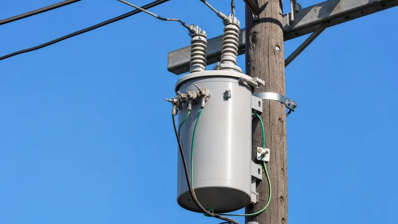
A single phase transformer for home use provides the split-phase secondary voltage required by residential consumer panels while isolating domestic premises from high-voltage primary distribution networks. In North American and Latin American markets, distribution utilities step down medium-voltage lines (typically 7.2 kV to 19.9 kV phase-to-ground) to 120/240V split-phase using either overhead pole-top transformers or low-profile pad-mounted cabinets.
For rural electrification, single-wire earth return (SWER) and two-wire single-phase lines represent the most economical topology, slashing capital expenditure by over 30% compared to three-phase extensions. For extensive technical analysis of remote network deployments, see our guide on pole mounted transformers for rural electrification.
Domestic transformer selection depends fundamentally on aggregate demand and diversity factors:
- Urban & Suburban Residences (25 kVA to 50 kVA): Typically shared among 2 to 4 households, accommodating central heat pumps, level-2 electric vehicle supply equipment (EVSE), and domestic appliances. Detailed residential load methodologies are explored in our residential transformer guide.
- Rural Farms & Dedicated Dwellings (15 kVA to 25 kVA): Dedicated to single properties where long low-voltage service runs would otherwise produce impermissible voltage drop ($>3\%$ under load).
- Light Commercial & Workshops (75 kVA to 100 kVA): Sized for substantial single-phase motor loads, agricultural grain dryers, or commercial refrigeration compressors.
How to Calculate kVA and Size a Single Phase Power Transformer
Calculating the required kVA for a single phase power transformer requires determining total connected load amperage, operating voltage, and applying statutory safety factors. Undersizing causes nuisance overcurrent trips and accelerated insulation degradation, while oversizing leads to poor power factor and continuous no-load core losses.
Follow this five-step engineering procedure to size your unit accurately:
- Determine the secondary load voltage ($V$): Identify whether the operational equipment requires 120V, 240V, or 480V.
- Calculate total load current ($I$): Sum the operating currents in amperes across all branch circuits. For inductive equipment like pumps or air compressors, obtain the running full-load amperes (FLA), not intermittent starting inrush.
- Calculate baseline apparent power ($VA$): Multiply load voltage by total current:$$VA = V \times I$$
- Apply the continuous duty sizing multiplier: Under National Electrical Code (NEC) Article 450 and standard engineering design practices, loads operating continuously for three hours or more must be factored at 125%:$$VA_{design} = VA \times 1.25$$
- Convert to kVA and round up to standard rating: Divide by 1,000 and select the next highest commercial rating:$$kVA = \frac{VA_{design}}{1000}$$For example, a machine shop load drawing 85A at 240V continuous duty produces: $240\text{ V} \times 85\text{ A} = 20,400\text{ VA} \times 1.25 = 25,500\text{ VA}$ ($25.5\text{ kVA}$). The engineer specifies a standard 37.5 kVA transformer.
Next steps: specifying and sourcing
When specifying a single phase power transformer for your upcoming infrastructure or industrial facility project, compiling a precise datasheet prevents costly field retrofits. Prepare your required continuous kVA rating, primary and secondary voltages, tap ranges, insulation thermal class (such as Class 180 or 220 for dry-type, or 65°C average winding rise for mineral-oil units), and target standards (IEEE C57, IEC 60076, or applicable NEMA standards).
Explore our engineering catalogue of high-efficiency oil-immersed transformers, compact dry-type transformers, and rugged utility-grade pole-mounted transformers engineered to international performance benchmarks. For bespoke engineering designs, detailed technical submittals, or budget pricing, submit your project schedule through our transformer quotation portal.
Frequently asked questions
What is the difference between a single phase and a three phase transformer?
A single phase transformer uses a single alternating voltage waveform and two conductors, whereas a three phase transformer utilises three alternating voltage waveforms separated by 120 electrical degrees across three or four conductors. Single-phase units are simpler and less expensive for low-power and residential applications, while three-phase units offer higher efficiency and power density for industrial heavy machinery.
Can I connect a single phase transformer to a three phase supply?
Yes, you can connect a single phase transformer across any two lines of a three-phase system (phase-to-phase) or between any one line and the system neutral (phase-to-neutral). However, this creates an unbalanced load on the upstream three-phase supply, which must be accounted for in system balancing.
What does split-phase 120/240V mean?
Split-phase 120/240V is a single-phase 3-wire distribution system produced by grounding the centre tap of a 240V transformer secondary winding. Measuring from either outer hot leg to the centre neutral yields 120V for standard appliances, while measuring across both hot legs yields 240V for heavy loads like heaters.
How do I choose between dry-type and oil-immersed single phase transformers?
Choose dry-type single-phase transformers for indoor installations, commercial structures, and clean industrial environments where fire safety and zero fluid leakage are paramount. Select oil-immersed transformers for outdoor utility poles, pad-mounted service entrances, and high-voltage distribution networks due to their superior dielectric strength and weather endurance.
Can a step down single phase transformer be wired in reverse to step up voltage?
Yes, most standard single phase transformers can be back-fed to operate as step-up units, provided voltage and frequency limits are respected. However, output voltage will be roughly 3% to 5% lower than expected under load because secondary windings have built-in turns compensation for internal voltage drop.
What size single phase transformer is needed to run a whole house?
A typical modern single-family home requires a single phase transformer rated between 25 kVA and 50 kVA. Homes with all-electric heating, multiple air conditioning systems, and fast electric vehicle charging infrastructure typically require at least a 37.5 kVA or 50 kVA dedicated distribution unit.
Tags: single phase power transformer 1 phase transformer 480 to 240 transformer single phase single phase step down transformer step down transformer


