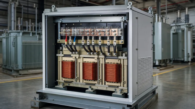
Key takeaways
- A buck and boost transformer operating as an autotransformer delivers up to ten times its nameplate kVA rating when stepping 208 V up to 240 V.
- Stepping 208 V up to 240 V requires an additive secondary boost of 32 V, which standard 120/240 V to 16/32 V units provide using series-connected secondary coils.
- Three-phase 208 V to 240 V conversions can be executed economically with two single-phase units in an open-delta bank or three units in a wye configuration.
- National Electrical Code (NEC) Article 450.4 mandates dedicated overcurrent protection and prohibits autotransformers without an earthed common conductor unless listed otherwise.
- Autotransformer connection does not provide galvanic isolation, meaning input and output share an electrical conductive path and common earth reference.
Quick answer: A buck and boost transformer 208 to 240 V setup uses low-voltage secondary windings wired in series with the 208 V supply lines to inject 32 V, producing a steady 240 V output. Because the core carries only the 32 V boost differential rather than the full load power, a compact 1.5 kVA unit can power a 10 kVA load.
Commercial distribution networks across North America frequently deliver 208Y/120 V three-phase power. However, industrial manufacturing machinery, commercial baking ovens, HVAC compressors, and high-output electric vehicle chargers are routinely engineered for nameplate ratings of 230 V or 240 V. Operating equipment designed for 240 V on a 208 V circuit causes a 13.3% undervoltage. Under standard induction motor equations, this voltage sag increases operating current by roughly 15%, causing resistive thermal losses ($I^2R$) to climb by over 30%, which triggers nuisance overcurrent tripping and significantly shortens winding insulation life.
While an isolation transformer can step the supply up, installing a buck and boost transformer 208 to 240 V system provides an efficient, economical alternative. By exploiting autotransformer principles, engineers can correct distribution line voltages with minimal footprint, low magnetic losses, and capital expenditures that are a fraction of the cost of full-capacity isolation equipment. For broader system context, explore our low voltage transformer engineering, sizing and selection guide.
Operating Principle of a Buck and Boost Transformer 208 to 240 V Connection
A buck-boost unit operates on standard magnetic induction but achieves high power density by electrically interconnecting its primary and secondary windings in the field as an autotransformer. In a conventional isolation unit, all energy transfers magnetically across the dielectric barrier from the primary core to the secondary core. In an autotransformer boost circuit, the vast majority of the load current flows directly via conductive copper interconnections, while the magnetic core transforms only the voltage difference required to elevate line potential.
To step voltage up from 208 V to 240 V, the system requires an additive boost of precisely 32 V:
$$\Delta V = V_{\text{out}} - V_{\text{in}} = 240\text{ V} - 208\text{ V} = 32\text{ V}$$
Standard off-the-shelf buck-boost dry-type units feature dual-voltage primary windings (120 × 240 V) and dual-voltage secondary windings (16 × 32 V). When the 120 V primary coils are wired in parallel across the incoming 208 V line, the 16 V secondary coils are connected in series aiding (in-phase) with the input. The incoming 208 V source feeds the primary, inducing a proportional voltage across the secondary windings. The secondary winding is placed in series with the load path, superimposing its 32 V potential directly onto the line conductor.
Because the physical transformer only processes the boost power (32 V multiplied by the load amperage), the physical core and coil need to be sized for only 13.3% of the total load kVA. The remaining 86.7% of the power is conducted straight through the copper circuit. Engineers designing dedicated single-phase branches should review the single phase transformer guide for foundational coil geometry and core loss calculations.
Worked Engineering Calculation: Sizing a 208 to 240 Transformer
Sizing a 208 to 240 transformer requires calculating the load current, verifying the secondary winding ampacity, and calculating the required physical kVA versus the allowable autotransformer pass-through kVA. Sizing must never be based strictly on load kW; full-load operating amperes (FLA) must dictate conductor selection.
Consider an industrial cooling compressor rated at 9.6 kW, single-phase 240 V, operating at a lagging power factor (PF) of 0.85.
- Calculate apparent load power (kVA):
$$\text{Load kVA} = \frac{9.6\text{ kW}}{0.85} = 11.29\text{ kVA}$$ - Calculate full-load operating current at 240 V:
$$I_{\text{load}} = \frac{11.29\text{ kVA} \times 1000}{240\text{ V}} = 47.04\text{ A}$$ - Calculate the required boost differential voltage:
$$V_{\text{boost}} = 240\text{ V} - 208\text{ V} = 32\text{ V}$$ - Calculate minimum physical core kVA rating:
$$\text{Transformer kVA} = \frac{V_{\text{boost}} \times I_{\text{load}}}{1000} = \frac{32\text{ V} \times 47.04\text{ A}}{1000} = 1.505\text{ kVA}$$ - Select standard manufacturer nameplate size:
A standard 1.5 kVA unit provides an internal secondary winding rating of:$$I_{\text{sec}} = \frac{1500\text{ VA}}{32\text{ V}} = 46.88\text{ A}$$Because 46.88 A is slightly below the continuous 47.04 A load, the engineer must step up to the next standard commercial size: a 2.0 kVA dry-type transformer with a secondary rating of 62.5 A at 32 V. - Determine total allowable autotransformer pass-through capacity:
$$\text{Capacity kVA} = \frac{240\text{ V} \times 62.5\text{ A}}{1000} = 15.0\text{ kVA}$$
The 2.0 kVA unit delivers 15.0 kVA of total pass-through capacity, providing comfortable thermal headroom for motor starting transients. If your application involves larger step-down utility voltages, such as 480 V distributions, refer to our 480V to 240V transformer sizing guide.
Single-Phase vs Three-Phase Buck-Boost Configurations
A buck and boost transformer 208 to 240 installation accommodates both single-phase two-wire/three-wire circuits and three-phase distribution systems using standard modular dry-type enclosures. The electrical topology chosen directly affects equipment count, terminal interconnections, and neutral stability.
For single-phase 208 V line-to-line circuits stepping up to 240 V line-to-line, only one single-phase transformer is required. The primary windings (the high-voltage terminals) are bridged across the two incoming 208 V lines, while the secondary windings (the low-voltage terminals) are wired in series with one of the ungrounded line conductors. The second phase conductor passes through unswitched, creating an asymmetric line-to-ground profile unless isolation is maintained.
For three-phase three-wire systems feeding 240 V delta loads from a 208Y/120 V supply, engineers can implement one of two distinct topologies:
- Open-Delta Configuration (Two Transformers): Utilises two identical single-phase buck-boost units connected across phases A-B and B-C, while phase B serves as a common reference. This setup provides an economical solution with minimum footprint, boosting line-to-line voltage on all three phases to 240 V. However, it introduces a slight phase-angle shift of approximately 1.5 to 2.5 degrees and creates minor voltage imbalances if line impedances vary.
- Wye (Star) Configuration (Three Transformers): Employs three identical single-phase units with secondaries inserted into each line conductor and primaries connected line-to-neutral. When stepping up three-phase lines, the system uses the 120 V line-to-neutral supply to boost line voltage. A 120 V to 138.5 V phase-to-neutral step results in $138.5\text{ V} \times \sqrt{3} = 240\text{ V}$ line-to-line. This topology maintains balanced line currents and avoids phase shifts, but it strictly requires an incoming, fully rated neutral conductor.
Buck-Boost Sizing Selection Table for 208V to 240V Loads
Selecting the correct transformer requires matching continuous load amperes to the secondary thermal current capacity of the autotransformer assembly. The following reference table specifies standard single-phase and three-phase (open-delta) sizing criteria for nominal 208 V to 240 V voltage conversion according to standard NEMA and UL 1561 parameters.
| System Configuration | Nominal Load Power (kW @ 0.9 PF) | Full Load Current (A) | Required Boost Voltage (V) | Individual Unit Nameplate (kVA) | Total Units Required | Maximum Pass-Through (kVA) |
|---|---|---|---|---|---|---|
| Single-Phase (1Ph) | 2.0 kW | 9.26 A | 32 V | 0.50 kVA | 1 | 3.75 kVA |
| Single-Phase (1Ph) | 5.0 kW | 23.15 A | 32 V | 1.00 kVA | 1 | 7.50 kVA |
| Single-Phase (1Ph) | 10.0 kW | 46.30 A | 32 V | 2.00 kVA | 1 | 15.00 kVA |
| Single-Phase (1Ph) | 15.0 kW | 69.44 A | 32 V | 3.00 kVA | 1 | 22.50 kVA |
| Three-Phase Open-Delta | 7.5 kW | 20.05 A | 32 V | 0.75 kVA | 2 | 8.31 kVA |
| Three-Phase Open-Delta | 15.0 kW | 40.10 A | 32 V | 1.50 kVA | 2 | 16.63 kVA |
| Three-Phase Open-Delta | 30.0 kW | 80.20 A | 32 V | 3.00 kVA | 2 | 33.26 kVA |
| Three-Phase Open-Delta | 50.0 kW | 133.66 A | 32 V | 5.00 kVA | 2 | 55.43 kVA |
All values assume a 120/240 V primary and 16/32 V secondary core arrangement wired for maximum series boost. For complete electrical balance on critical motor loads, engineers should evaluate overall distribution stability via our industrial power system installation guide.
NEC Compliance, Grounding, and Overcurrent Protection
Installing an autotransformer configuration requires strict adherence to National Electrical Code (NEC/NFPA 70) regulations to ensure personnel safety and operational reliability. Because an autotransformer lacks galvanic separation between primary and secondary circuits, improper connections risk dangerous floating potentials.
NEC Article 450.4 regulates autotransformer installations. Under Clause 450.4(A), each ungrounded input conductor must be equipped with an overcurrent protective device (OCPD), such as a moulded-case circuit breaker (MCCB) or fuse assembly, rated at not more than 125% of the rated full-load input current. If 125% does not correspond to a standard fuse or breaker rating under NEC 240.6, the next higher standard rating is permissible.
Grounding and bonding demand precision under NEC 250.24 and 250.30:
- No Separately Derived System: An autotransformer connected buck and boost transformer 208 to 240 circuit does not establish a separately derived system because there is no isolated secondary neutral. Consequently, the output circuit must not have an independent neutral-to-ground bond installed at the transformer enclosure. Adding an output bond creates parallel neutral paths and ground loops that trigger residual current circuit breakers (RCCBs) and violate code.
- Common Earthed Conductor: NEC Article 210.9 specifies that branch circuits supplied by autotransformers must have an earthed conductor that is electrically continuous from the source network to all output points, unless the assembly is listed as an engineered power conversion unit.
- Enclosure Grounding: The metal enclosure of the dry-type unit must be bonded directly to the equipment grounding conductor (EGC) sized in accordance with NEC Table 250.122, based on the upstream overcurrent device rating.
Common Installation Pitfalls and Factory Acceptance Checks
Field commissioning errors with a 208 to 240 transformer typically stem from terminal misidentification, polarity inversions, or saturation under motor inrush. Factory testing and systematic site verification prevent catastrophic winding flashovers.
- Subtractive Wiring Polarity Error (Bucking Instead of Boosting): Buck-boost transformers depend on additive polarity. If lead X1 and lead X4 are reversed during termination, the induced secondary voltage will subtract from the source voltage rather than add to it. A 208 V supply will drop to 176 V instead of climbing to 240 V. Running an undervoltage test at low potential before applying full load verifies output polarity.
- Inrush Saturation Tripping: Autotransformers feature very low series impedance (%Z), typically under 2%. When supplying commercial motors or industrial induction heating equipment, instantaneous starting inrush currents (6× to 8× FLA) can drive the core into magnetic saturation, creating transient overcurrents that trip fast-acting magnetic circuit breakers. Upstream breakers should feature adjustable short-time delay or motor-duty magnetic trip curves.
- Phase Disconnect Verification: In open-delta banks, disconnecting the common Phase B conductor while phases A and C remain energised can induce high back-EMF potentials across open coils, endangering field technicians. Multi-pole disconnect switches that break all ungrounded phase conductors simultaneously are required.
Next steps: specifying and sourcing
To receive an accurate quotation for your voltage conversion project, send our engineering team your specific electrical parameters: incoming supply voltage, required output voltage, total full-load amperage or kW with power factor, phase configuration (single-phase or three-phase wye/delta), ambient operating temperature, and required NEMA/IP enclosure class. Our factory manufactures precision-engineered dry-type transformers and integrated HV/LV switchgear assemblies fully certified to IEC 60076, IEEE C57, and UL standards. Visit our transformer quotation page to submit your single-line diagram, or contact our application engineers at our engineering contact portal for immediate technical sizing assistance.
Frequently asked questions
Can a buck and boost transformer 208 to 240 provide an isolated neutral?
No, a buck and boost transformer operating in an autotransformer configuration does not provide galvanic isolation or create a separately derived neutral. The secondary coils are electrically tied directly to the incoming supply lines. If an isolated neutral or zero-sequence isolation is required, a full isolation transformer must be used.
Why is a buck-boost transformer so much smaller than an isolation transformer?
It is smaller because its core and windings only transform the 32 V voltage differential rather than the entire load power. Roughly 87% of the load current passes directly through the copper interconnections conductively. This allows a 1.5 kVA or 2.0 kVA physical unit to safely supply a 10 kVA to 15 kVA electrical load.
Can I use two single-phase buck-boost units to step up three-phase 208 V to 240 V?
Yes, two single-phase buck-boost units can be connected in an open-delta bank to boost three-phase 208 V to 240 V line-to-line. This is a common, cost-effective commercial method for three-wire loads, though it introduces a negligible phase-angle shift of approximately 1.5 to 2.5 degrees.
What happens if I wire a 208 to 240 transformer backwards?
Wiring the secondary leads in reverse polarity causes subtractive induction, transforming the unit into a bucking circuit that reduces voltage. Instead of stepping 208 V up to 240 V, the output will drop by 32 V down to 176 V, which can stall induction motors and trigger upstream circuit protection.
What overcurrent protection sizing is required for autotransformer installations?
According to NEC Article 450.4, each ungrounded input conductor must be protected by an overcurrent device rated at no more than 125% of the input full-load current. If 125% does not align with standard breaker sizes, NEC 240.6 allows the next higher standard rating.
Tags: buck and boost transformer 208 to 240 208 to 240 transformer voltage conversion autotransformer dry-type transformer


