Key takeaways
- A true two-phase system has two sinusoidal voltages 90 degrees apart and delivers constant instantaneous power to a balanced load, like three-phase.
- In three-wire two-phase systems the shared return conductor carries 1.414 times the phase current, a major reason three-phase replaced it.
- North American 120/240 V service is single-phase split-phase: its two 120 V legs are 180 degrees apart from one center-tapped winding.
- Two hot lines taken from a 208Y/120 V system are 120 degrees apart and are single-phase 208 V, often loosely called two-phase.
- A Scott-T transformer pair converts three-phase to true two-phase using a main winding with center tap and a teaser winding at 86.6 percent voltage.
Quick answer: 2 phase power is an AC system with two voltages displaced 90 degrees, carried on three or four wires. It was used in early networks of the 1890s and survives only in a few legacy and special industrial installations. What most people call two-phase today is either 120/240 V split-phase, which is single-phase, or two lines of a three-phase system, such as 208 V.
The phrase two-phase power causes more confusion than any other in AC distribution. Electricians use it for split-phase residential service, tariff documents in some countries use it for a two-wire supply taken from a three-phase network, and textbooks use it for a 90-degree system that almost nobody installs any more. All three meanings are in active use, and each implies different wiring.
This guide sorts out what two-phase electricity actually is, how it compares with single-phase and three-phase, how two-phase is still produced where needed, and how to read a specification that says two-phase. It is for engineers, contractors and buyers who need to be sure what they are wiring or ordering.
What Is Two-Phase Electricity?
A two-phase system is a polyphase AC system in which two voltages of equal magnitude and frequency are displaced by 90 electrical degrees. If phase A is V × sin(ωt), phase B is V × sin(ωt − 90°), which is the same as a cosine wave.
Two-phase power was developed in the late 1880s for early induction motors, because two currents in quadrature produce a rotating magnetic field. The Niagara Falls hydroelectric plant that opened in 1895 generated two-phase power at 25 Hz. Within a few decades three-phase systems displaced two-phase almost everywhere because they need less conductor material for the same power.
Is two-phase power a thing today? Yes, but rarely:
- A few legacy urban networks and old industrial buildings kept two-phase service well into the late 20th century.
- Some induction furnaces, servo drives and special test systems use two-phase supplies produced locally.
- Small two-phase servo motors and AC control motors are fed from a single-phase supply with a capacitor creating the second, 90-degree phase.
A key property of a balanced two-phase system is constant instantaneous power. For a resistive load, p = VmIm[sin²(ωt) + cos²(ωt)] = VmIm, which has no ripple. Single-phase power pulsates at twice line frequency; two-phase and three-phase do not. That is why motors on polyphase supplies run smoother than single-phase motors. Waveform behavior for three-phase is illustrated in our 3-phase wave guide.
Two-Phase Wiring: Three-Wire and Four-Wire Systems
Two-phase wiring came in two forms, and the difference shows why the system lost out.
Four-wire two-phase
Each phase has its own pair of conductors, effectively two independent single-phase circuits with a 90-degree relationship. Simple, but it needs four conductors to carry the power that three-phase carries on three.
Three-wire two-phase
One conductor of each phase is shared as a common return. With phase current I in each outer wire, the common wire carries the phasor sum of two currents 90 degrees apart: Icommon = √2 × I = 1.414 × I. The voltage between the two outer wires is also √2 × V. The common conductor must be larger, and the system is unbalanced in its conductor loading.
| Arrangement (same power P, phase voltage V) | Conductors | Conductor currents (I = P / V) | Highest voltage between conductors |
|---|---|---|---|
| Single-phase 2-wire | 2 | I, I | V |
| Two-phase 4-wire | 4 | I/2 in each | V within each pair |
| Two-phase 3-wire | 3 | I/2, I/2 and 0.707 I in the common | 1.414 V between outer wires |
| Three-phase 3-wire (line voltage V) | 3 | 0.577 I in each | V |
At the same line voltage and losses, three-phase three-wire delivers the same power with about 75 percent of the conductor material of single-phase or four-wire two-phase, with every conductor equally loaded. That saving, plus simpler transformers and motors, drove universal adoption of three-phase. Practical three-phase distribution is covered in the 3-phase 4-wire system guide.
Single Phase vs Two Phase: Is Split-Phase Two-Phase?
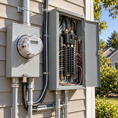
The most common confusion is calling North American 120/240 V residential service two-phase. It is not. Split-phase is single-phase.
A split-phase supply comes from one transformer secondary winding with a grounded center tap. The two ends are each 120 V to the neutral, and measured against the neutral they are 180 degrees apart, but they are the same waveform, one simply referenced from the other end. There is only one phase angle in the system, and the 240 V between the two legs is a single sinusoid. A true two-phase supply would have 90 degrees between its voltages.
| Feature | Single-phase 230 V | Split-phase 120/240 V | True two-phase | Three-phase |
|---|---|---|---|---|
| Phase displacement | None | 180 degrees (same phase, reversed reference) | 90 degrees | 120 degrees |
| Conductors | L, N | L1, L2, N | 3 or 4 | 3 or 4 |
| Rotating field possible | No (needs capacitor) | No | Yes | Yes |
| Constant power | No | No | Yes | Yes |
| Typical use | Homes outside North America | North American homes | Legacy, special industrial | All industry and grids |
A split-phase supply cannot start an induction motor without a capacitor or auxiliary winding, which proves it is single-phase. For the full wiring and transformer details, see 240V single-phase and split-phase explained.
Note: work on residential service equipment must follow local code and be done by a licensed electrician.
Double Phase and 2-Phase Voltage from a Three-Phase Supply
The second common meaning of two-phase or double phase is a supply consisting of two line conductors from a three-phase network, with or without the neutral.
- 208 V from 208Y/120 V: two lines of a wye system are 120 degrees apart, giving
120 × √3 = 208 Vbetween them. Apartment buildings in North America often receive 120/208 V three-wire service: two phases plus neutral. - 400 V from 400/230 V: two lines of a European system give 400 V single-phase, used for some welders and large heaters.
- Two-phase tariffs: in some countries with 127/220 V networks, utilities sell a two-line connection as a "two-phase" service.
Electrically, a load connected across two lines of a three-phase system is a single-phase load. The voltage between the two wires is one sinusoid. What makes these supplies distinctive is the neutral behavior: in a 120/208 V three-wire service with balanced 120 V loads on each leg, the neutral carries current equal to the phase current, not zero, because the two currents are 120 degrees apart rather than 180. This is a frequent surprise and is explained with examples in the 208V single-phase guide.
So 2 phase voltage might mean 240 V (split-phase), 208 V (two lines of 208Y/120), 400 V (two lines of 400/230) or a genuine quadrature system. Always ask for the line-to-line and line-to-neutral voltages and the phase angle before quoting equipment.
Two-Phase vs Three-Phase: Why Three-Phase Won
Comparing two-phase vs three-phase power on engineering grounds explains why every modern grid uses three phases.
- Conductor economy: three-phase three-wire transmits a given power with 75 percent of the copper needed by single-phase or four-wire two-phase at the same line voltage and loss.
- Balanced conductors: in a balanced three-phase system all line conductors carry equal current and the neutral carries none; three-wire two-phase always has an oversized common conductor.
- Transformers: three-phase transformers on a single three-limb core are smaller and cheaper than equivalent two-phase banks.
- Motors: three-phase induction motors have better winding utilization and lower torque ripple.
- Rectification: three-phase bridges give six-pulse DC with low ripple; two-phase full-wave gives four-pulse.
Both systems share the advantages of constant power and a rotating field, which single-phase lacks. The advantages of three-phase over two-phase are economic and practical, not fundamental, but they were decisive.
Three-phase voltage relationships, including line-to-line and line-to-neutral values, are summarized in the 3-phase voltage guide. If a site has single-phase supply only and needs three-phase motors, the options are reviewed in converting 1-phase to 3-phase.
How Is Two-Phase Power Produced Today? The Scott-T Transformer
Where a true two-phase supply is needed, it is derived from the three-phase grid with a Scott-T connection. A Scott-T transformer is a pair of single-phase transformers connected so that a balanced three-phase input yields two output voltages 90 degrees apart, or the reverse.
- The main transformer has its primary connected between two lines (say B and C) with a center tap.
- The teaser transformer has its primary connected from the main's center tap to the third line (A), with
√3/2 = 86.6 percentof the main primary turns. - The two secondaries, wound for equal voltage, produce outputs in quadrature.
Worked example: a 400 V three-phase supply feeds two 230 V, 50 kVA single-phase loads that must be in quadrature for a test rig. The main primary is rated 400 V across B-C; the teaser primary is rated 400 × 0.866 = 346 V. Each secondary is 230 V at 50 kVA, carrying 50,000 / 230 = 217 A. On the three-phase side, total load is 100 kVA, so line current is 100,000 / (1.732 × 400) = 144 A, balanced on all three lines.
The same connection works in reverse to balance two large single-phase loads, such as railway traction feeders or induction furnaces, across a three-phase supply. Related phase-conversion transformer arrangements are covered in the phase-shifting transformer guide.
Four-Phase and Six-Phase Power: Where Higher Phase Counts Appear
Four phase power is a two-phase system with each winding center-tapped, producing four voltages 90 degrees apart around a common neutral. It was used briefly in some early systems and appears today in stepper motor drives and certain electronic circuits rather than power distribution.
Six-phase and twelve-phase systems are more significant in industry:
- Six-phase (six-pulse) rectifiers use a transformer with two secondaries or a center-tapped wye to create six voltages 60 degrees apart, reducing DC ripple.
- Twelve-pulse rectifiers combine a delta and a wye secondary, 30 degrees apart, to cancel 5th and 7th harmonics in the supply current. They are common in large drives, electrolysis plants and DC traction.
- Six-phase transmission has been studied for higher power per right-of-way but is not in general use.
| Phase count | Displacement | Main application today |
|---|---|---|
| 1 (and split-phase) | - | Residential and light loads |
| 2 | 90 degrees | Legacy networks, servo and control motors |
| 3 | 120 degrees | All generation, transmission and industry |
| 4 | 90 degrees, center-tapped | Stepper drives, electronics |
| 6 / 12 | 60 / 30 degrees | Rectifier transformers, large drives |
Phase-shifted secondaries for multi-pulse rectifiers are a transformer design question; the vector groups involved are explained in delta-wye transformer guide.
Next Steps: Specifying and Sourcing When a Spec Says Two-Phase
When a drawing, tender or customer request says two-phase, clarify before quoting:
- Ask for line-to-line and line-to-neutral voltages and the phase angle between conductors (90, 120 or 180 degrees).
- Confirm the number of wires and whether a neutral is present and grounded.
- Identify the supply transformer type: center-tapped single-phase, three-phase wye or a Scott-T pair.
- For special loads needing true two-phase or phase-balancing, specify a Scott-T or other phase-conversion transformer with kVA per output, voltages and frequency.
MARS builds oil-immersed transformers and dry-type transformers in single-phase, three-phase and special connections to IEC 60076 and ANSI/IEEE variants. Send the connection diagram and load data through the quote request, and our engineers will confirm the winding arrangement.
Frequently asked questions
Is two-phase power a thing?
Yes, but it is rare. True two-phase power uses two voltages 90 degrees apart and was common in the 1890s before three-phase took over. Today it survives in a few legacy installations and special industrial loads. Most references to two-phase actually mean split-phase residential service or two lines of a three-phase system.
What is the difference between single-phase and two-phase?
Single-phase has one sinusoidal voltage and pulsating power, so it cannot create a rotating field without a capacitor. True two-phase has two voltages 90 degrees apart, delivering constant power and a rotating field for motors. Split-phase 120/240 V service is single-phase even though it has two hot legs.
Is 240V two-phase?
No. North American 240 V comes from a single center-tapped transformer winding and is single-phase. The two 120 V legs are 180 degrees apart relative to neutral because they are opposite ends of the same winding, not separate phases. A 240 V circuit uses two hot conductors but one phase.
What is the difference between 2-phase and 3-phase power?
Two-phase uses two voltages 90 degrees apart; three-phase uses three voltages 120 degrees apart. Both deliver constant power, but three-phase needs less conductor material than four-wire two-phase for the same power and loss, has balanced line currents and allows smaller transformers, which is why it became the global standard.
How many wires does two-phase power use?
True two-phase systems use either four wires, two independent pairs, or three wires with a shared common return. In the three-wire version the common conductor carries 1.414 times the phase current. Split-phase residential service also uses three wires, two hots and a neutral, but it is single-phase.
What is double phase power?
Double phase usually means a supply with two line conductors from a three-phase network, such as 208 V from a 208Y/120 V system or 400 V from a 400/230 V system. Electrically it is single-phase between the two lines. Some utilities use the term in tariffs for two-line residential connections.
Written and reviewed by the MARS application engineering team in Shanghai, who specify and test transformers, switchgear, substations and battery storage for projects in 40+ countries. Last updated .
Tags: 2 phase power two phase vs three phase single phase vs two phase what is two phase electricity four phase power