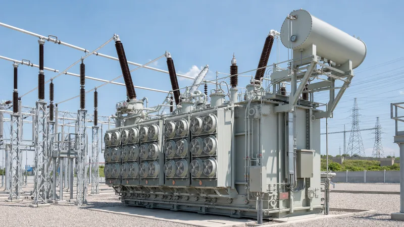
Key takeaways
- A phase shifting transformer alters the transmission voltage angle without changing voltage magnitude, enabling precise active power flow control over parallel lines.
- Quadrature boosters insert a voltage component 90 degrees out of phase with the system line-to-neutral voltage to control megawatt dispatch.
- Two-core symmetrical phase shifting transformers decouple tap-changer voltage stresses from transmission line lightning impulse withstand levels.
- Standardised under IEC 60076-57-1202 and IEEE C57.135, these units require dual differential protection relays to accommodate dynamic phase displacement.
- Internal impedance shifts dynamically across the tap range, requiring system fault level studies at both minimum and maximum phase angle extremes.
Quick answer: A phase shifting transformer (PST), often termed a quadrature booster, regulates active power transfer across alternating current transmission networks by adjusting the phase angle between input and output terminals. By injecting a variable quadrature voltage perpendicular to the system voltage, a PST redirects loop flows and prevents thermal overloads on parallel circuits.
In meshed high-voltage networks, electrical current naturally divides in inverse proportion to line impedance rather than line capacity. When a low-impedance overhead line runs parallel to a higher-impedance underground cable or an older line, power flow imbalances frequently create thermal bottlenecks. Utility planners use a phase shifting transformer to override this natural physical dispatch, directing power onto underutilised transmission assets without the capital expenditure of constructing new rights-of-way. Operating principles, core configurations, vector relationships, and factory specification requirements govern how these specialised assets integrate into utility grids alongside standard transmission transformer installations.
Operating Principles: How a Phase Shifting Transformer Controls Power Flow
A phase shifting transformer controls real power transfer by inserting an intentional voltage phase displacement (α) between the source and load buses. In an alternating current transmission line connecting bus 1 (sending voltage $V_1$) and bus 2 (receiving voltage $V_2$) separated by total circuit reactance $X$, active power flow ($P$) is defined by the classical power-angle equation:
$$P = \frac{V_1 V_2}{X} \sin(\delta + \alpha)$$
where $\delta$ is the natural load angle of the system and $\alpha$ is the phase shift angle imposed by the PST. Under normal conditions without an intervening phase shifter ($\alpha = 0$), power flows strictly as dictated by system generation and impedance. Introducing a positive advance angle increases the effective electrical driving angle, forcing additional megawatts down that circuit; conversely, a negative retard angle backs down power, deflecting energy onto alternative parallel corridors.
This active control relies on quadrature voltage injection. The transformer shifting mechanism extracts a sample voltage from two phases and introduces it in series with the third phase. Because the line-to-line voltage in a three-phase system lags or leads the line-to-neutral voltage by 90 electrical degrees, cross-connecting these windings yields a quadrature voltage ($V_Q$) perpendicular to the system phase-to-neutral voltage ($V_P$). Adding $V_Q$ to $V_P$ shifts the resultant output voltage vector without significantly altering system voltage magnitude in symmetrical designs.
Single-Core vs Two-Core Topologies: Symmetrical vs Asymmetrical Design
Phase shifting transformer configurations divide into single-core and two-core topologies depending on network operating voltage, throughput rating, and tap changer dielectric limits. A single-core PST houses both the exciting winding and the series winding on a single magnetic structure, making it cost-effective and compact for sub-transmission systems below 138 kV. However, this design directly exposes the on-load tap changer (OLTC) to high-voltage line surges and lightning impulses.
For transmission grids operating at 230 kV to 500 kV, utilities specify two-core phase shifting transformers. This topology splits the magnetic circuit into an exciting transformer (connected in shunt) and a series transformer (connected in line). The exciting transformer steps down the line voltage to an intermediate level (typically 10 kV to 35 kV), where a standard distribution-grade OLTC adjusts the quadrature voltage magnitude before feeding the series transformer exciting winding.
| Design Parameter | Single-Core Asymmetrical | Single-Core Symmetrical | Two-Core Symmetrical |
|---|---|---|---|
| Voltage Range | 33 kV to 145 kV | 69 kV to 145 kV | 138 kV to 500 kV |
| Throughput Rating | 50 MVA to 250 MVA | 100 MVA to 400 MVA | 300 MVA to 1,500 MVA |
| Phase Angle Range | Up to ±15° | Up to ±20° | Up to ±40° |
| OLTC Dielectric Stress | Full system line BIL | Full system line BIL | Intermediate voltage BIL (10–35 kV) |
| Voltage Magnitude Shift | Yes (varies with angle) | None (pure phase rotation) | None (pure phase rotation) |
| Footprint & Tank Structure | Single tank, compact | Single tank, moderate | Dual tank or partitioned single tank |
Symmetrical designs use double series windings to advance and retard the vector symmetrically around the incoming voltage phasor. Asymmetrical units simply add a quadrature component at 90 degrees to the incoming phase, which causes the output phase voltage to rise slightly in magnitude according to the hypotenuse calculation $\sqrt{V_P^2 + V_Q^2}$.
Worked Power Flow Calculation: Controlling Megawatts Across Parallel Feeders
A worked engineering example demonstrates how injecting phase displacement corrects parallel transmission overloads. Consider two parallel 400 kV transmission paths connecting Substation A to Substation B, transferring a total load of 1,200 MW. Path 1 consists of an overhead line with a reactance of $X_1 = 16\,\Omega$. Path 2 is a mixed cable and overhead line corridor with a reactance of $X_2 = 32\,\Omega$. The natural system load angle between Substation A and Substation B is $\delta = 10^\circ$ (0.1745 rad).
Under natural physical dispatch without a phase shifting transformer:
- Calculate the natural branch power flows using the line reactances:
- $P_1 = \frac{(400\text{ kV})^2}{16\,\Omega} \times \sin(10^\circ) = 10,000 \times 0.1736 = 1,736\text{ MW}$ theoretical capacity, yielding an actual natural split of:
- Current divides inversely with reactance: $I_1 / I_2 = X_2 / X_1 = 32 / 16 = 2$.
- Consequently, Path 1 carries $P_1 = 1,200 \times \frac{32}{16+32} = 800\text{ MW}$.
- Path 2 carries $P_2 = 1,200 \times \frac{16}{16+32} = 400\text{ MW}$.
- If Path 1 has a thermal continuous rating of only 600 MW, it operates in an overloaded state by 200 MW.
- Install a two-core symmetrical phase shifting transformer in series with Path 1 to back down flow by applying a retard angle ($-\alpha$). We seek to establish $P_1 = 600\text{ MW}$ and deflect 200 MW into Path 2 ($P_2 = 600\text{ MW}$).
- Set the branch equation for Path 1 including the PST internal reactance ($X_{PST} = 4\,\Omega$, total $X_{1,\text{new}} = 20\,\Omega$):
- $P_1 = 600\text{ MW} = \frac{(400\text{ kV})^2}{20\,\Omega} \times \sin(10^\circ - \alpha) = 8,000 \times \sin(10^\circ - \alpha)$
- $\sin(10^\circ - \alpha) = \frac{600}{8,000} = 0.075$
- $10^\circ - \alpha = \arcsin(0.075) = 4.30^\circ$
- $\alpha = 10^\circ - 4.30^\circ = +5.70^\circ$ (retard angle)
By imposing a phase retard shift of $\alpha = 5.70^\circ$, Path 1 power drops from 800 MW to exactly 600 MW, bringing the line within safe thermal limits while increasing Path 2 throughput to 600 MW without tripping line breakers.
On-Load Tap Changer Integration and Vector Regulation
The on-load tap changer functions as the control actuator of a phase shifting transformer, altering the number of active turns on the exciting winding to vary quadrature voltage magnitude. Standard vacuum-type OLTCs compliant with IEC 60214-1 regulate the transformer shifting mechanism through a dedicated reversing switch. When the reversing switch alternates polarity, the injected quadrature vector pivots by 180 electrical degrees, transitioning the PST smoothly from advance mode (leading phase angle) to retard mode (lagging phase angle).
Because the OLTC operates inside the intermediate voltage loop of two-core designs, it avoids high transient recovery voltages during line faults. However, the step voltage and circulating current within the tap mechanism remain substantial. Design engineers must size tap selector contacts for peak throughput MVA, particularly during through-fault conditions where short-circuit currents surge through the series windings. Mechanical interlocks and advanced motor drive mechanisms ensure synchronous operation across all three phases to prevent unbalance and neutral point drift.
Protection Schemes and Factory Acceptance Testing for PSTs
Phase shifting transformer protection presents distinct challenges because conventional percentage differential relays (ANSI 87T) trip incorrectly when phase displacement varies dynamically across tap positions. Standard differential algorithms rely on static phase matching matrices. In a PST, because the phase shift ranges continuously from $-\alpha$ to $+\alpha$, differential relays must receive instantaneous tap position telemetry via digital encoders to calculate dynamic compensation matrices in real time, as detailed in our guide on transformer protection schemes.
Differential protection architectures typically separate into two zones:
- Overall Differential Protection (87PST): Monitors currents entering and leaving the primary bushings, compensated dynamically for OLTC tap positions.
- Internal Core Differential Protection: Dedicated standard percentage differential relays for both the series transformer and the shunt exciting transformer cores.
Factory acceptance testing follows IEC 60076-57-1202 clause 10 and IEEE C57.135 standards. Routine procedures detailed in our overview of power transformer testing protocols require phase angle displacement verification at every single tap position using high-precision vector analysers, no-load loss and excitation current measurement, zero-sequence impedance verification across full retard and advance extremes, and lightning impulse tests applied to the series and shunt terminals simultaneously.
Specification Checklist for Utility and EPC Tenders
Writing an engineering procurement requisition for a phase shifting transformer requires strict definition of operational and impedance envelopes. System planners must supply manufacturers with boundary conditions rather than static values, as impedance changes as a function of tap position.
| Specification Field | Required Engineering Parameter | Reference Standard |
|---|---|---|
| Throughput Rating | Continuous MVA and emergency overload profile (e.g. 600 MVA ONAN / 800 MVA ONAF) | IEC 60076-1 clause 5.1 |
| System Voltage | Nominal & highest operating voltage (e.g. 400 kV / 420 kV) | IEC 60076-1 clause 5.2 |
| Phase Shift Range | Continuous variable angle (e.g. ±25° in 33 symmetrical steps) | IEC 60076-57-1202 clause 6 |
| Core Construction | Two-core dual-tank or single-tank partitioned design | IEEE C57.135 Table 2 |
| Impedance Profile | Short-circuit impedance at 0° shift and at maximum shift (±α max) | IEC 60076-5 clause 4 |
| Insulation Level (BIL) | Series terminals (e.g. 1,425 kV peak), exciting neutral (e.g. 325 kV) | IEC 60076-3 Table 2 |
| OLTC Mechanism | In-tank vacuum diverter switch with motorized control & SCADA tap output | IEC 60214-1 clause 5 |
| Cooling Scheme | ONAN / ONAF / OFAF or ODAF arrangements | IEC 60076-2 clause 4 |
Next steps: specifying and sourcing
Specifying a phase shifting transformer requires detailed load flow analyses, transient stability simulations, and clear definition of impedance boundaries across the entire regulation angle. When preparing your tender or project requisition, compile your system single-line diagrams, short-circuit levels, maximum continuous and emergency MVA requirements, and desired phase angle variation range. Our engineering team reviews bespoke utility specifications to construct high-efficiency power transformers and complete transformer substations engineered to IEC and IEEE standards. Visit our transformer quotation page or contact our technical sales engineers directly to discuss vector topology, cooling specifications, and production lead times for your transmission project.
Frequently asked questions
What is the primary purpose of a phase shifting transformer?
A phase shifting transformer controls real power flow across parallel alternating current transmission corridors. By adjusting the phase angle between terminal voltages, it redistributes megawatt power flows to eliminate line overloads and balance transmission grid utilisation.
How does a phase shifting transformer differ from a standard power transformer?
Standard power transformers primarily change voltage magnitude between systems while maintaining a fixed phase angle. In contrast, a phase shifting transformer regulates the phase angle shift between input and output, leaving terminal voltage magnitudes virtually unchanged in symmetrical configurations.
What is the difference between symmetrical and asymmetrical phase shifting transformers?
Symmetrical phase shifting transformers alter the vector phase angle without modifying the output voltage magnitude. Asymmetrical phase shifting transformers inject a quadrature voltage at a fixed 90-degree angle, which inadvertently increases the output voltage magnitude alongside the phase shift.
Why are two-core designs preferred for high-voltage phase shifting transformers?
Two-core designs isolate the on-load tap changer from extreme transmission grid voltage stresses by stepping the voltage down to an intermediate level. This reduces tap changer insulation requirements and protects the switching mechanism from line lightning impulses.
How does tap position affect phase shifting transformer impedance?
Impedance varies significantly across the operating range, reaching its lowest value at the neutral zero-shift tap and rising to its maximum value at full advance or retard angles. Grid fault calculations must evaluate both impedance extremes.
Which international standards govern phase shifting transformers?
Phase shifting transformers are primarily specified, built, and tested according to IEC 60076-57-1202 and IEEE C57.135. These standards define core topologies, short-circuit withstand requirements, and tap-dependent acceptance testing procedures.
Tags: phase shifting transformer transformer shifting power transformers grid power flow OLTC


