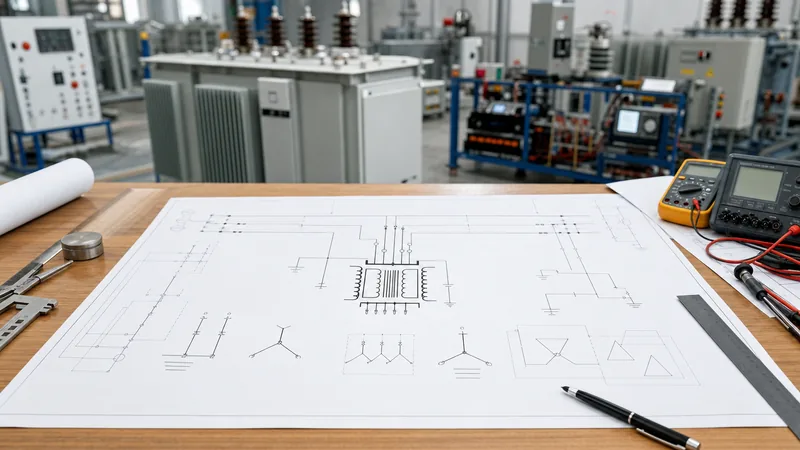
Key takeaways
- The iron core transformer symbol depicts two inductive windings separated by two solid parallel lines representing high-permeability ferromagnetic laminations.
- International standard IEC 60617 uses simplified overlapping circles or scalloped coils, whereas North American IEEE Std 315 depicts looped arcs alongside dual core bars.
- Solid parallel lines indicate a laminated iron or electrical steel core, whereas dashed lines denote ferrite and the total absence of lines indicates an air-core unit.
- The symbol of autotransformer differs fundamentally from isolated transformers by displaying a single continuous coil tapped at an intermediate point along the magnetic core path.
- Polarity markings, indicated by instantaneous voltage reference dots adjacent to winding terminals, define phase alignment and directional winding relationships essential for parallel operation.
Quick answer: The iron core transformer symbol consists of two parallel inductor coils separated by two solid, parallel straight lines representing the magnetic ferromagnetic core. Standardised under IEC 60617 and IEEE Std 315, this graphical notation signifies high magnetic permeability, mutual flux coupling, and galvanic isolation between primary and secondary electrical circuits.
In electrical engineering, single-line diagrams (SLDs), schematic diagrams, and wiring prints require universal graphical representations to convey operational characteristics rapidly. Without unambiguous symbology, design engineers and field technicians cannot determine whether a transformer uses an air core, a powdered ferrite core, or cold-rolled grain-oriented (CRGO) electrical steel laminations. The presence of the iron core lines tells the engineer immediately that the device relies on a ferromagnetic core to concentrate magnetic flux, yielding high coupling efficiency, specific magnetising reactance, and measurable core losses. Understanding the nuances of this symbol across international standards ensures error-free design execution, correct protective relay configuration, and seamless commissioning across utility and industrial power systems.
Standards Overview: IEC 60617 vs IEEE 315 Iron Core Transformer Symbol
Schematic conventions for the iron core transformer symbol diverge between international standards, primarily governed by IEC 60617 across Europe and global IEC territories, and IEEE Std 315 (ANSI Y32.2) throughout North America. In IEEE Std 315 representations, the primary and secondary windings are drawn as series of semi-circular looped arches facing each other, positioned adjacent to two or three solid parallel bars that designate the ferromagnetic laminated core. Conversely, IEC 60617 favours a simplified functional presentation: either two overlapping circles representing magnetically coupled windings in single-line diagrams, or dual multi-scallop windings placed beside solid boundary lines in detailed circuit schematics.
Both systems convey the same foundational physical reality governed by Faraday’s law of induction and Ampère’s circuital law. In both standards, the core lines do not represent electrical connections; they depict the non-conductive, low-reluctance magnetic circuit that guides the alternating mutual flux ($Φ$). While an open space between winding inductors denotes an air-core device (permeability $μ_r ≈ 1$), the solid lines confirm a high-permeability medium ($μ_r$ typically between 2,000 and 40,000 for silicon steel). When specifying grid apparatus via our transmission transformer engineering guide, adhering strictly to the contract-specified drafting standard prevents dangerous misunderstandings regarding winding isolation and grounding points.
Anatomy of the Iron Core Transformer Symbol on Schematics
The anatomy of an iron core transformer symbol communicates four critical engineering attributes: winding topology, core composition, winding polarity, and tap architecture. The inductive coils denote the physical copper or aluminium windings, with the number of drawn scallops occasionally indicating high-voltage (HV) versus low-voltage (LV) sides, although drawing scale does not quantify actual physical turn ratios. The solid parallel lines represent the CRGO steel core pack, whose material behaviour dictates hysteresis and eddy current performance as detailed in our technical guide to transformer core design and losses.
Terminal conventions and polarity dots provide phase-angle reference. A black dot placed at the terminal of the primary winding and another at the secondary winding mark identical instantaneous electrical polarity. When alternating current flows into the primary dot-marked terminal, current simultaneously flows out of the secondary dot-marked terminal, establishing an in-phase relationship (zero-degree phase displacement). Additional anatomical variants include:
- Fixed taps: Intermediate lead lines projecting directly from points along the winding arcs, establishing set transformation ratios.
- Off-circuit tap changers (OCTC): Detached tap selector terminals linked by a movable contact arm symbol.
- On-load tap changers (OLTC): Flag indicators or resistor-bridged switch symbols indicating tap changes can execute while carrying full rated load current.
- Electrostatic shields: A dashed or dotted single line located between the winding and core bars, terminated with a direct chassis earth symbol to denote ground-plane capacitive shielding.
Engineers reviewing detailed internal plant drawings can consult our overview of transformers internal components to correlate these graphic elements with physical tanks, core clamps, and lead structures.
Comparing Transformer Core and Winding Symbols
Electrical schematics employ differentiated core lines and coil arrangements to distinguish between isolation transformers, variable reactors, instrument units, and auto-coupled systems. Selecting or interpreting the correct graphic ensures system designers correctly calculate fault impedances, inrush currents, and insulation coordinates.
| Transformer Type | Schematic Core Symbol | Core Line Specification | Governing Standard | Standard Magnetic Material |
|---|---|---|---|---|
| Air Core Transformer | Zero lines between coils | No lines (empty dielectric space) | IEEE 315 / IEC 60617 | Air / non-magnetic former ($μ_r = 1$) |
| Iron Core Transformer | Two solid parallel lines | Continuous solid lines (0.5 mm line weight) | IEEE 315 / IEC 60617 | CRGO laminated silicon steel |
| Ferrite Core Transformer | Two dashed or dotted parallel lines | Segmented lines denoting ceramic matrix | IEEE 315 / IEC 60617 | Sintered manganese-zinc / nickel-zinc |
| Variable Iron Core | Solid lines with diagonal arrow | Solid core bars traversed by 45° arrow | IEEE 315 / IEC 60617 | Adjustable laminated slug or plunger |
| Step-Down Autotransformer | Single tapped coil with solid lines | Dual solid lines parallel to single winding | IEEE 315 / IEC 60617 | CRGO wound or stacked laminations |
| Shielded Isolation Transformer | Solid core lines plus dashed ground plane | Two solid lines flanked by grounded dashed line | IEEE 315 / IEC 60617 | Grain-oriented silicon steel with copper shield |
As shown in the table, the distinct line treatments prevent confusion between high-frequency switch-mode transformers (ferrite cores) and heavy power equipment like power transformers and substation distribution units.
Symbol of Autotransformer vs Two-Winding Iron Core Units
The symbol of autotransformer differs fundamentally from a two-winding transformer symbol because it features a single, continuous inductive winding that acts simultaneously as both the primary and secondary electrical circuit. Instead of two physically separate coils separated by core lines, the schematic symbol displays one common winding set alongside the standard dual iron core lines, with an intermediate tap connection protruding from the side of the winding stack. This direct metallic connection between circuits means that an autotransformer lacks galvanic isolation.
Understanding this symbolic distinction is critical for electrical safety and grounding calculations. In a standard iron core transformer symbol, the independent winding circuits demonstrate complete dielectric barrier isolation, limiting short-circuit transfer and isolating zero-sequence return currents. In contrast, the symbol of autotransformer highlights direct electrical continuity between the HV and LV systems. When contractors implement system step-down configurations via our guide on how to connect step down transformers, observing whether the print shows two isolated windings or an autotransformer symbol dictates whether common neutrals, grounding conductors, and overcurrent protections comply with IEC 60364 or National Electrical Code (NEC / NFPA 70) Article 450.
How to Read Polarity Dots, Tappings, and Vector Groups
Reading a multi-phase iron core transformer symbol on three-line or single-line distribution drawings requires systematic decoding of terminal labels, winding interconnections, and phase shift designations. For three-phase distribution units—such as commercial dry-type transformers—vector groups are marked directly adjacent to the schematic graphic to define the phase displacement between HV and LV windings.
- Locate terminal naming conventions: Check terminal identification letters per IEC 60076 (1U, 1V, 1W for HV; 2U, 2V, 2W for LV) or IEEE C57.12.00 (H1, H2, H3 for HV; X1, X2, X3 for LV).
- Identify instantaneous polarity dots: Verify dot alignment. Dots located on identical physical ends (e.g., H1 and X1) confirm additive or subtractive polarity standards, indicating whether secondary induced EMF reinforces or opposes the primary circuit under external interconnection.
- Determine internal winding topology: Inspect how individual phase coils connect. A delta arrangement appears as an enclosed triangle ($Δ$ or D/d), whereas a wye (star) configuration appears as three coils joined at a common neutral point (Y/y).
- Decode vector group notations: Interpret alphanumeric codes (such as Dyn11 or Ynd1). A Dyn11 code indicates a Delta-connected HV winding, a Wye-connected LV winding with an accessible neutral (n), and a 30-degree LV phase lead relative to the HV voltage vector (corresponding to the 11 o’clock clock-face position).
- Examine tapping switch positions: Locate tap terminals along the HV winding symbol to identify whether tapping switches operate off-circuit or via an active diverter-switch OLTC mechanism.
Next steps: specifying and sourcing
When preparing single-line diagrams, engineering bid packages, and procurement requisitions, accurately conveying the correct transformer symbol ensures manufacturing specifications match your precise electrical requirements. Our engineering team designs and manufactures utility-grade power transformers, high-efficiency oil-immersed transformers, and cast resin dry-type units built to IEC 60076 and IEEE C57 standards. To obtain a fully engineered design proposal complete with approved schematic diagrams, vector group verifications, and factory test plans, submit your single-line schematics, voltage ratios, impedance values, and site conditions through our transformer quote portal or contact our technical sales department directly.
Frequently asked questions
What does the iron core transformer symbol look like?
An iron core transformer symbol consists of two inductor winding coils placed side-by-side or face-to-face, separated by two solid parallel lines. These lines represent the high-permeability magnetic iron or electrical steel core that couples the electrical circuits.
What do the parallel lines in a transformer symbol mean?
The parallel lines represent the magnetic core material between the windings. Two solid parallel lines indicate a ferromagnetic laminated silicon steel core, dashed parallel lines designate a powdered iron or ferrite core, and no lines represent an air-core transformer.
How does the symbol of autotransformer differ from an isolation transformer?
The symbol of autotransformer displays a single continuous winding with an intermediate tap terminal, set beside the core lines. In contrast, an isolation transformer symbol shows two separate, physically disconnected windings that possess no direct electrical connection.
What do polarity dots mean on an iron core transformer schematic?
Polarity dots indicate the instantaneous relative phase direction of current and voltage between the primary and secondary windings. Current entering the dot on the primary winding induces current that exits the corresponding dot on the secondary winding, maintaining zero-degree instantaneous phase agreement.
What is the difference between IEC and IEEE transformer symbols?
IEEE Std 315 uses curved, looped inductor arcs placed beside parallel bars to depict core-type transformers. IEC 60617 typically uses two overlapping circles for single-line diagrams, or scalloped winding outlines beside boundary lines on detailed schematic prints.
Tags: iron core transformer symbol symbol of autotransformer power transformers electrical schematics IEC 60617


