Key takeaways
- A standard three-phase transformer selection chart correlates nominal kVA capacity directly to line voltages, full-load amps, and circuit protection thresholds.
- Three-phase full-load current is determined using the fundamental equation I = S / (V × √3), where S is apparent power in volt-amperes and V is line-to-line voltage in volts.
- National Electrical Code (NEC) Table 450.3(B) sets maximum overcurrent protection for low-voltage transformers at 250% for primary-only protection, or 125% primary with 125% secondary breaker sizing.
- Circuit breaker trip ratings must tolerate short-term magnetising inrush current, typically reaching 8 to 12 times rated current for 100 milliseconds, without nuisance tripping.
- Standard percent impedance (%Z) values range from 4.0% to 5.75% for medium-voltage distribution units, dictating symmetrical fault levels at downstream switchgear.
Quick answer: A transformer selection chart provides electrical engineers and EPC contractors with a direct reference correlating apparent power (kVA), line-to-line voltages, full-load currents, and recommended primary and secondary protective device ratings. It establishes baseline full-load amperes (FLA) to ensure upstream and downstream switchgear are sized correctly under both continuous loading and transient inrush conditions.
Specifying distribution transformers requires precise balance between thermal capacity, allowable voltage drop, prospective fault levels, and protective coordination. Selecting an undersized unit leads to elevated winding temperatures, premature dielectric degradation, and nuisance overcurrent trips. Conversely, gross oversizing increases capital expenditure, core no-load losses, and the mechanical rating required for downstream switchboards. Whether you are engineering a commercial facility, integrating renewable plants, or specifying a packaged transformer substation, consulting a structured selection reference eliminates guesswork during initial design phases.
Three-Phase Transformer Selection Chart
A comprehensive transformer selection chart maps standard distribution transformer capacities against primary medium-voltage systems and secondary low-voltage systems to display operating currents and standard thermal thresholds. For single-phase evaluations or specific reference to mid-tier commercial ratings, consult our guide on 75 kVA transformer amps.
The table below details standard 50 Hz and 60 Hz ratings, secondary current at standard 415 V and 480 V configurations, recommended secondary main circuit breakers, and typical short-circuit impedance (%Z) conforming to IEC 60076-1 clause 5.4 and IEEE C57.12.00 Table 5:
| Capacity (kVA) | Full-Load Current @ 415V (A) | Full-Load Current @ 480V (A) | Nominal %Z (IEC/IEEE) | Recommended LV Breaker (A) | Full-Load Current @ 11kV (A) |
|---|---|---|---|---|---|
| 100 | 139.1 | 120.3 | 4.00% | 160 | 5.25 |
| 160 | 222.6 | 192.5 | 4.00% | 250 | 8.40 |
| 250 | 347.8 | 300.7 | 4.00% | 400 | 13.12 |
| 315 | 438.3 | 378.9 | 4.00% | 500 | 16.53 |
| 500 | 695.6 | 601.4 | 5.00% | 800 | 26.24 |
| 630 | 876.5 | 757.8 | 5.00% | 1000 | 33.07 |
| 800 | 1113.0 | 962.3 | 5.00% | 1250 | 41.99 |
| 1000 | 1391.2 | 1202.8 | 5.00% | 1600 | 52.49 |
| 1250 | 1739.0 | 1503.5 | 5.75% | 2000 | 65.61 |
| 1600 | 2226.0 | 1924.5 | 5.75% | 2500 | 83.98 |
| 2000 | 2782.5 | 2405.6 | 5.75% | 3200 | 104.97 |
| 2500 | 3478.1 | 3007.0 | 5.75% | 4000 | 131.22 |
| 3150 | 4382.4 | 3788.9 | 6.25% | 5000 | 165.33 |
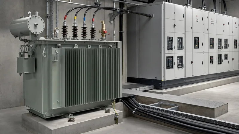
For installations where physical footprint and fire safety are paramount, such as indoor basements or industrial vaults, engineers frequently specify a cast-resin dry-type transformer, whereas outdoor and utility-grade distribution typically relies on an oil-immersed transformer.
How to Calculate Full-Load Current and kVA Requirements
To select an asset accurately from a selection chart, an engineer must first calculate total connected load, apply operational diversity, and determine full-load rated current. In a balanced three-phase AC power network, line current is calculated directly using the apparent power equation:
I = S / (V × √3)
Where I is the continuous line current in amperes (A), S is the apparent power in volt-amperes (VA), and V is the nominal line-to-line root-mean-square (RMS) voltage in volts (V). When planning an installation, follow this step-by-step engineering procedure:
- Sum the continuous and non-continuous loads: Aggregate the total connected real power (kW) across motor loads, lighting, heating, and IT equipment. Apply a standard 125% continuous duty multiplier to continuous loads lasting three hours or longer per NEC Article 215.3.
- Determine operating power factor: Divide total active power (kW) by the facility displacement power factor (typically 0.85 to 0.95 lagging) to establish the base apparent demand in kVA.
- Account for future growth and harmonics: Apply an expansion margin (normally 20% to 25%) and evaluate non-linear loads. If non-linear electronic rectifiers exceed 15% of the total load, specify an appropriate K-factor rating (e.g., K-4 or K-13) to prevent localized eddy-current winding overheating.
- Select the standard kVA rating: Round the calculated demand up to the nearest standardized manufacturing rating (e.g., 500, 630, 800, or 1000 kVA).
Transformer Breaker Sizing Chart and Overcurrent Protection Rules
A transformer breaker sizing chart provides immediate baseline ampacity thresholds for primary and secondary switchgear. Circuit breaker ratings must balance continuous thermal carrying capability with the severe transient requirements imposed by core energisation.
Under both IEC 60364-4-43 and NEC Article 450.3, protective thresholds depend entirely on whether overcurrent protection is installed strictly on the primary winding or on both primary and secondary windings. The following transformer breaker size chart highlights typical protective device sizing rules under NEC Table 450.3(A) and (B):
| Location | System Voltage | Primary Protection Only | Primary Protection with Secondary | Secondary Protection Rating |
|---|---|---|---|---|
| Primary Circuit | Over 1000V (MV) | 300% (Fuse: 200%) | 600% (Fuse: 300%) | N/A |
| Secondary Circuit | Over 1000V (MV) | Not Applicable | Conducted via primary | 250% (Fuse: 150%) |
| Primary Circuit | 600V or Less (LV) | 167% (for I < 9A) to 250% | 250% maximum | N/A |
| Secondary Circuit | 600V or Less (LV) | Not Applicable | Conducted via primary | 125% (Next standard size up) |
When selecting protective devices, transformer breaker sizing must ensure that the primary breaker's long-time pickup accommodates 100% to 125% of rated primary FLA, while the short-time and instantaneous pick-up thresholds remain above the transformer inrush curve. The inrush envelope typically peaks at 8× to 12× FLA for a duration of 0.1 seconds (IEC 60076-8). For complex networks incorporating dual supplies or rings, review our comparative analysis of radial feed vs loop feed topologies to establish proper protection zones.
Worked Engineering Example: Transformer Circuit Breaker Sizing
Applying accurate transformer circuit breaker sizing ensures both code compliance and stability against false tripping during across-the-line energisation. Consider a practical industrial example: specifying primary and secondary circuit breakers for a 1500 kVA, three-phase oil-immersed substation transformer stepping down from 11 kV to 415 V (50 Hz), with an impedance of 5.75%.
Step 1: Calculate Rated Primary and Secondary Full-Load Amperes:
- Primary FLA (11,000 V): I_prim = 1,500,000 / (11,000 × 1.732) = 78.73 A
- Secondary FLA (415 V): I_sec = 1,500,000 / (415 × 1.732) = 2,087.05 A
Step 2: Calculate Secondary Circuit Breaker Rating:
Per standard industrial design practice and IEC 60947-2, the secondary main circuit breaker (usually an Air Circuit Breaker, or ACB) is sized for continuous full-load carrying capacity with an overload relay set between 1.0× and 1.15× secondary FLA. Multiplying 2,087 A by 1.15 yields 2,400 A. Therefore, an engineer selects a standard 2500 A four-pole ACB with adjustable electronic trip unit settings (LSI: Long-time, Short-time, Instantaneous).
Step 3: Calculate Primary Vacuum Circuit Breaker Sizing:
For medium-voltage protection on the 11 kV feeder, a vacuum circuit breaker (VCB) or fused switch-disconnector is applied. According to NEC 450.3(A) where secondary protection is provided, the primary overcurrent device can be rated up to 600% of primary FLA for circuit breakers, though factory engineering best practice limits this to 150% to 250% to maintain close thermal backup:
- Design primary breaker trip rating: 78.73 A × 2.0 = 157.46 A. A standard 200 A or 630 A frame VCB with a relay pickup dialed to 100 A is selected.
- Check Magnetising Inrush: Inrush point = 10 × 78.73 A = 787.3 A at 0.1 s. The relay time-current characteristic curve (TCC) must verify that the 50/51 overcurrent curve sits safely above 787 A at 100 ms to avoid nuisance tripping upon line switching. Detailed coordination guidelines can be explored further in our guide to transformer protection.
Key Engineering Considerations Beyond the Selection Table
Consulting a standard transformer breaker sizing chart provides thermal baselines, but electrical plant engineers must also assess operational constraints that impact equipment life and safety. Ignoring these real-world phenomena often results in accelerated dielectric breakdown or destructive arc-flash incidents.
- Impedance (%Z) and Downstream Fault Levels: Transformer nameplate impedance directly determines prospective short-circuit current: I_sc = FLA / (%Z / 100). For a 1000 kVA, 415 V unit with 5% impedance, symmetrical fault current reaches 27.8 kA. If downstream switchgear is only rated for 25 kA breaking capacity, the transformer impedance must be specified at 5.75% or 6.0% to suppress fault energy to acceptable ratings.
- Temperature Rise and Altitude Derating: Transformers engineered to IEC 60076 are rated for ambient temperatures not exceeding 40°C and altitudes below 1000 metres above sea level. For installations in elevated mining or high-altitude sites, air cooling efficiency drops due to lower atmospheric density. According to IEEE C57.96, dry-type units must be derated by 0.5% for every 100 metres above 1000 metres unless oversized winding radiators or forced air cooling (AF) are integrated.
- Harmonic Load Factor (K-Factor): Non-linear switching loads produced by variable speed drives (VSDs) and uninterruptible power supplies (UPS) induce harmonic eddy-current losses in windings. When sourcing transformers for critical power infrastructure or industrial automation, a factory evaluation of stray load losses per IEEE C57.110 is essential. When planning integrated indoor substations, refer to our comprehensive technical manual on unit substation engineering.
Procurement and Engineering RFQ Specification Checklist
When submitting a Request for Quotation (RFQ) to a transformer factory, missing electrical parameters lead to delayed design revisions or incorrectly built core-coil assemblies. Engineers can use the following checklist directly in procurement documentation:
- Rated Apparent Power: Nominal continuous kVA/MVA capacity along with cooling class designations (e.g., ONAN/ONAF for liquid-filled, AN/AF for dry-type).
- Voltage Profile and Vector Group: Primary nominal voltage, secondary no-load voltage, connection type, and vector group (e.g., Dyn11, Dyn1, or YNd11).
- Tapping Range: Off-Circuit Tap Changer (OCTC) typically at ±2 × 2.5%, or On-Load Tap Changer (OLTC) with step percentages for active grid voltage regulation.
- Guaranteed Impedance and Losses: Specified %Z within manufacturing tolerances (IEC allows ±10% on impedance), guaranteed maximum no-load core losses (P0), and full-load winding losses (Pk) at reference temperature (75°C or 120°C).
- Environmental Classification: Ingress protection rating (e.g., IP00, IP23, IP54), ambient temperature range, seismic zone qualification, and corrosion protection (C3 to marine-grade paint system).
- Instrumentation and Protection Fittings: Winding temperature indicators (WTI), oil temperature indicators (OTI), double-float Buchholz relay, pressure relief device (PRD) with trip microswitches, and magnetic oil level gauge (MOG).
Next steps: specifying and sourcing
Accurate selection of your distribution transformer and its corresponding switchgear ensures high operational efficiency, system reliability, and electrical safety across decades of service life. When you are ready to finalize your project requirements or obtain factory-direct technical drawings, contact our engineering sales department. Provide your system single-line diagram (SLD), voltage levels, site ambient conditions, and preferred loss standards via our request a quote page or get in touch directly through our contact page. Our factory engineering team will furnish comprehensive technical datasheets, outline dimensional drawings, and optimized equipment selections tailored to your operating environment.
Frequently asked questions
What is a transformer selection chart?
A transformer selection chart is an engineering reference table that matches apparent power ratings in kVA to corresponding line voltages, full-load currents, short-circuit impedances, and suitable primary and secondary protective circuit breakers.
How do you size a circuit breaker for a transformer?
Size the secondary breaker to carry 100% to 125% of the secondary full-load current without exceeding cable thermal capacity. Size the primary breaker between 125% and 250% of rated primary current depending on code requirements, ensuring its instantaneous trip setting clears the transformer magnetising inrush curve.
What size breaker is needed for a 500 kVA 480V transformer?
A 500 kVA transformer at 480 V produces 601.4 A of full-load current. Under standard electrical codes permitting a 125% multiplier for secondary main protection, an 800 A frame circuit breaker with adjustable trip settings dialed to approximately 750 A is standard.
Why does a transformer require breaker sizing above its full-load current?
Overcurrent protection must accommodate magnetising inrush currents that occur during core flux saturation at energisation. These transient currents reach 8 to 12 times normal full-load current for 100 milliseconds, which would trip breakers sized strictly at nominal full-load amperage.
What is the standard impedance for distribution transformers?
Standard impedance ranges between 4.0% and 5.0% for distribution transformers up to 1000 kVA, and between 5.75% and 6.25% for units rated from 1250 kVA up to 3150 kVA, conforming to IEC 60076 and IEEE C57 standards.
Can I use primary overcurrent protection only without a secondary breaker?
Yes, electrical codes such as NEC 450.3(B) allow primary-only protection if the primary overcurrent device is set to no more than 250% of rated primary current for systems under 600 V. However, dual primary and secondary protection is strongly recommended for improved selectivity and closer thermal protection.
Tags: transformer selection chart transformer breaker size chart transformer breaker sizing chart transformer breaker sizing transformer circuit breaker sizing


