Key takeaways
- Transformer connections determine secondary voltage magnitude, phase angular displacement, and zero-sequence harmonic circulation across three-phase systems.
- Standard vector group designations follow IEC 60076-1, where uppercase letters denote high-voltage windings, lowercase letters denote low-voltage windings, and numbers indicate phase lag in 30-degree increments.
- Dyn11 and Dyn1 configurations provide an inherent zero-sequence path that traps triplen harmonics within the delta winding, protecting grid-side infrastructure.
- Parallel operation of three-phase transformers requires identical phase displacement, matching polarity, equal voltage ratios, and percentage impedances matched within a 10 percent tolerance per IEC 60076-1 clause 10.4.
- Residential split-phase systems use a center-tapped secondary winding to supply both 120 V line-to-neutral and 240 V line-to-line single-phase loads simultaneously.
Quick answer: Transformer connections define the electrical coupling between primary and secondary winding phases to establish voltage transformation, phase displacement, and earthing paths. Configured predominantly as Delta (D/d) or Wye (Y/y), these three-phase arrangements govern harmonic mitigation, fault-current behaviour, and system stability under unbalanced loads.
In alternating-current power systems, the arrangement of transformer connections dictates how voltage levels transform between generation, transmission, and utilisation nodes. Engineers selecting winding topologies must balance earthing requirements, fault clearance strategies, and electromagnetic compatibility across network interfaces. Whether establishing an interconnection on a transmission transformer or configuring a commercial supply, correct terminal assignment ensures reliable power delivery while preventing catastrophic short-circuit conditions during synchronisation.
Understanding Transformer Phase and Vector Groups (IEC 60076-1)
A transformer phase displacement describes the angular time lag between the line-to-neutral voltage vector of the high-voltage (HV) terminal and the corresponding vector of the low-voltage (LV) terminal. Standardised under IEC 60076-1 clause 6, these connections are expressed through alphanumeric vector groups using a 12-hour clock face convention, where each hour represents a 30-degree phase shift.
The notation identifies winding configurations through concise rules:
- Uppercase letters: Designate the primary or higher-voltage winding (e.g., D = Delta, Y = Wye/Star, Z = Zigzag, N = Neutral brought out).
- Lowercase letters: Designate the secondary or lower-voltage winding (e.g., d = Delta, y = Wye/Star, z = Zigzag, n = Neutral brought out).
- Clock numbers (0 to 11): Indicate the phase displacement of the LV winding relative to the HV winding, taken as 12 o'clock (0 degrees). A value of 11 corresponds to a 330-degree lag, which is equivalent to a 30-degree lead (+30°), whereas a value of 1 corresponds to a 30-degree lag (-30°).
- Auto-transformers: Denoted by the prefix "auto" or by an assigned letter combination such as YNa0.
For example, a Dyn11 connection specifies a delta-connected HV winding, a star-connected LV winding with a neutral terminal brought out to a separate bushing, and an LV line voltage that leads the HV line voltage by 30 degrees. Selecting the correct vector group is vital when integrating equipment alongside an existing power transformer fleet to avoid massive cross-circulating currents.
Delta and Wye Transformer Connections: Operational Trade-offs
Delta and star configurations deliver distinct operational benefits regarding harmonic propagation, neutral stabilising capabilities, and load balancing across network phases. In a delta configuration, line voltage equals phase winding voltage ($V_L = V_{ph}$), while line current equals $\sqrt{3}$ times phase current ($I_L = \sqrt{3} \times I_{ph}$). Conversely, in a wye arrangement, line voltage equals $\sqrt{3}$ times phase voltage ($V_L = \sqrt{3} \times V_{ph}$), and line current is identical to phase winding current ($I_L = I_{ph}$).
The following decision table compares standard three-phase configurations to assist project engineers during network specification:
| Configuration | IEC Vector Group | Phase Shift (°) | Neutral Grounding | Primary Application |
|---|---|---|---|---|
| Delta – Star Grounded | Dyn11, Dyn1 | +30° / -30° | LV Neutral Earthed | Industrial plants, utility LV distribution networks |
| Star Grounded – Star Grounded | YNyn0 | 0° | Both Neutrals Earthed | Inter-tie transmission links with common neutral |
| Delta – Delta | Dd0, Dd6 | 0° / 180° | Ungrounded / Grounding Bank | Heavy industrial plants, isolated secondary power |
| Star – Delta | Ynd1, Ynd11 | -30° / +30° | HV Neutral Earthed | Generator step-up (GSU) utility substations |
| Star – Zigzag Grounded | Yzn11 | +30° | LV Neutral Earthed | Networks with severe single-phase unbalance |
A delta-wye configuration represents the industry baseline for stepping down distribution voltages. The closed delta loop traps third-harmonic currents ($150\text{ Hz}$ in $50\text{ Hz}$ systems or $180\text{ Hz}$ in $60\text{ Hz}$ systems), preventing triplen harmonic flux distortion from transferring onto upstream medium-voltage feeders.
Reading a Step Down Transformer Connection Diagram
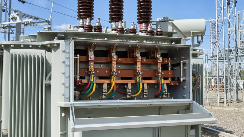
A step down transformer connection diagram illustrates physical lead routing from internal winding tap coils to exterior high-voltage and low-voltage terminal bushings. According to IEEE C57.12.70 and IEC 60076-1 standards, terminals are designated with alphanumeric identifiers: $H_1, H_2, H_3$ (or $1U, 1V, 1W$) for the high-voltage lines, and $X_1, X_2, X_3$ (or $2U, 2V, 2W$) for the low-voltage lines, alongside neutral terminals labeled $H_0$ ($1N$) or $X_0$ ($2N$).
In a standard step-down Dyn11 arrangement, the internal HV windings form a closed ring. Phase A connects across $H_1-H_2$, Phase B across $H_2-H_3$, and Phase C across $H_3-H_1$. On the low-voltage side, winding terminals $X_1, X_2, X_3$ provide three-phase four-wire service ($400/230\text{ V}$ or $480/277\text{ V}$), with the common ends joined at the $X_0$ neutral bushing. When reviewing an installation plan for a step-down transformer connection, engineers must verify subtractive or additive polarity markings stamped on the nameplate to prevent reverse phase energisation.
Wiring a Transformer 3 Phase: Commissioning Procedure
Properly wiring a transformer 3 phase system demands rigorous adherence to electrical safety protocols and phase sequencing checks prior to applying grid potential. Field errors during conductor termination or tap-changer alignment can cause line-to-line faults or phase cancellation.
- De-energise and verify electrical isolation: Implement lockout/tagout (LOTO) protocols on primary MV switchgear and secondary LV distribution breakers. Use a calibrated high-voltage proximity detector and earthing leads to discharge residual capacitive charges.
- Perform pre-connection insulation resistance tests: Apply a $2.5\text{ kV}$ or $5\text{ kV}$ DC test instrument between HV windings to earth, LV windings to earth, and between HV and LV windings. Minimum acceptable insulation values must meet the guidelines set out in IEEE C57.152 Table 1.
- Verify transformer turns ratio (TTR): Confirm that voltage transformation ratios on all active de-energised tap changer (DETC) positions align with factory nameplate data within a $\pm 0.5\%$ variance per IEC 60076-1 clause 10.3.
- Terminate medium-voltage conductors: Land MV phase cables onto primary bushings ($H_1, H_2, H_3$) using calibrated torque wrenches according to the manufacturer's specified bolt torque values. Maintain standard electrical clearance distances inside the cable compartment.
- Terminate low-voltage conductors and neutral: Fasten phase busbars or cables to secondary terminals ($X_1, X_2, X_3$). Ground the $X_0$ neutral bushing to the main substation earth grid using appropriately sized copper conductor compliant with NFPA 70 (NEC) Article 250.30.
- Conduct phase rotation and vector verification: Energise from the HV side with secondary open-circuited. Measure phase-to-phase and phase-to-neutral voltages, confirming clockwise phase rotation (A-B-C) via a phase rotation meter prior to load pickup.
Reviewing our detailed guide on distribution transformer specifications ensures that field crews follow appropriate cable lug dimensions and thermal class limits during execution.
Residential Transformer Diagram and Single-Phase Systems
A residential transformer diagram outlines a single-phase three-wire split secondary system powered from a high-voltage utility lateral. Widely adopted across North America and regions influenced by ANSI/IEEE frameworks, this setup steps down primary distribution voltages (such as $13.8\text{ kV}$ or $7.2\text{ kV}$ line-to-neutral) to a $120/240\text{ V}$ utilisation level.
The secondary winding consists of two independent $120\text{ V}$ coils wound in series on a common laminated core leg. The junction between these coils connects to an insulated center tap brought out to the $X_2$ bushing, which is bonded to the neutral earthing electrode at the property service entrance. Terminal $X_1$ to $X_2$ delivers $120\text{ V}$ for lighting, electronics, and general receptacle circuits, while $X_2$ to $X_3$ provides an opposing $120\text{ V}$ supply ($180°$ out of phase). Connecting across the outer lines ($X_1$ to $X_3$) delivers the full $240\text{ V}$ potential required for heavy domestic loads like heat pumps, water heaters, and electric vehicle chargers. More comprehensive details on single-phase magnetic circuits can be found in our single-phase transformer engineering guide.
Parallel Operation of a 3 Phase Distribution Transformer
Connecting more than one 3 phase distribution transformer in parallel on a common busbar increases total substation capacity and redundancy, but requires strict adherence to four fundamental design criteria. Mismatched parameters generate circulating currents that overheat windings and trigger premature protection trips even under zero-load conditions.
Successful parallel coupling requires:
- Identical vector group and phase displacement: Units must have identical phase shifts (e.g., paralleling Dyn11 with Dyn11). Paralleling a Dyn11 unit with a YNyn0 unit introduces a 30-degree phase discrepancy, creating a short-circuit line-to-line voltage differential of $2 \times V \times \sin(15°) \approx 51.8\%$ of system voltage.
- Identical voltage ratios: Turns ratios must be matched across identical primary and secondary taps to prevent circulating currents caused by differing no-load induced EMFs.
- Identical phase sequence: Both units must share identical A-B-C terminal phase rotation.
- Proportional percentage impedance (%Z): The load sharing between two units operates inversely proportional to their respective internal impedances.
Worked Engineering Calculation: Parallel Load Sharing
Consider two units feeding a shared 400 V switchboard with an aggregate system load of $S_L = 1800\text{ kVA}$ at $0.85$ power factor lagging:
- Transformer A: $S_{n,A} = 1000\text{ kVA}$, impedance $Z_A = 5.0\%$
- Transformer B: $S_{n,B} = 1000\text{ kVA}$, impedance $Z_B = 5.75\%$
The total equivalent admittance of the paralleled bank is calculated by:
$$\frac{1}{Z_{eq}} = \frac{S_{n,A}}{Z_A} + \frac{S_{n,B}}{Z_B} = \frac{1000}{0.05} + \frac{1000}{0.0575} = 20000 + 17391 = 37391\text{ kVA}$$
The individual load taken by Transformer A ($S_A$) is:
$$S_A = S_L \times \left( \frac{S_{n,A} / Z_A}{1 / Z_{eq}} \right) = 1800 \times \left( \frac{20000}{37391} \right) = 962.8\text{ kVA}$$
Transformer A operates at $\frac{962.8}{1000} = 96.3\%$ of its continuous thermal rating.
The individual load taken by Transformer B ($S_B$) is:
$$S_B = S_L \times \left( \frac{S_{n,B} / Z_B}{1 / Z_{eq}} \right) = 1800 \times \left( \frac{17391}{37391} \right) = 837.2\text{ kVA}$$
Transformer B operates at only $\frac{837.2}{1000} = 83.7\%$ of its continuous thermal rating. This 15 percent variance demonstrates why IEC 60076-1 clause 10.4 recommends keeping impedance values matched within $\pm 10\%$ to ensure balanced thermal stress across assets.
Next steps: specifying and sourcing
When specifying custom winding configurations for substation builds, project managers must define the primary and secondary operating voltages, fundamental basic insulation level (BIL), continuous kVA rating, short-circuit percentage impedance (%Z), and preferred vector group. Review our complete selection of oil-immersed distribution transformers, high-efficiency dry-type transformers, and utility-grade pad-mounted transformers engineered to international IEC and IEEE standards. Contact our application engineering department at [email protected] or submit your single-line diagram (SLD) directly through our dedicated transformer quote portal to obtain detailed drawings and compliance documentation.
Frequently asked questions
What is the most common 3-phase transformer connection?
The Delta-Wye (Dyn11 or Dyn1) connection is the most prevalent three-phase configuration in power distribution. It provides a stable secondary neutral point for single-phase loads while isolating triplen zero-sequence harmonics within the primary delta winding.
Can you parallel transformers with different vector groups?
Transformers with different vector groups can only be paralleled if their internal connections can be re-pinned to achieve identical secondary phase displacement. Paralleling units with unequal phase shifts, such as a Dyn11 (+30 degrees) and a Dyn1 (-30 degrees), causes extreme short-circuit circulating currents.
Why is the delta connection used on the high-voltage side of distribution transformers?
A delta connection on the high-voltage primary winding traps zero-sequence third harmonics, preventing line-voltage distortion across the upstream grid. It also eliminates the need for a primary neutral wire, reducing distribution installation costs.
What happens if phase sequence is reversed when wiring a transformer 3 phase?
Reversing phase rotation (wiring A-C-B instead of A-B-C) causes downstream three-phase motors to spin in reverse, which damages equipment such as pumps, fans, and compressors. It also creates dead short circuits if paralleled with an existing correctly phased system.
What does Dyn11 mean on a transformer nameplate?
Dyn11 indicates a delta-connected high-voltage winding (D), a wye-connected low-voltage winding (y) with a neutral point brought out (n), and an LV phase voltage vector that leads the HV vector by 30 degrees (clock position 11).
Tags: transformer connections wiring a transformer 3 phase 3 phase distribution transformer step down transformer connection diagram transformer phase


