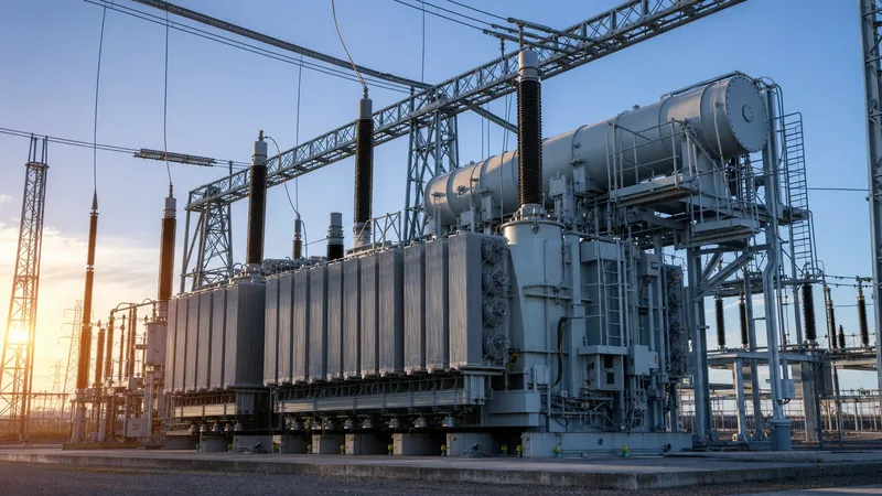
Key takeaways
- The largest power transformer units operate up to 1,100 kV ultra-high voltage direct current (UHVDC) and alternate current (UHVAC) grids with single-phase capacities reaching 1,000 MVA.
- A typical biggest electrical transformer can weigh over 500 tonnes during transit and exceed 800 tonnes when fully assembled and filled with dielectric oil.
- Designing ultra-large transformers requires continuous disc winding, step-lap magnetic cores, and forced-directed oil and forced air (ODAF) cooling configurations to dissipate heat flux exceeding 1.5 W/cm².
- Dielectric margins for the largest electrical transformer equipment must endure basic lightning impulse insulation levels (BIL) exceeding 2,400 kV in accordance with IEC 60076-3.
- Transportation logistics, road clearances, and bridge load-bearing limits dictate the absolute physical boundary dimensions of ultra-large transformers more than core electromagnetic capacity.
Quick answer: The largest power transformer units in commercial service are 1,100 kV ultra-high voltage (UHV) converter and transmission transformers, boasting individual single-phase ratings between 500 MVA and 1,000 MVA, with assembled operational weights exceeding 800 metric tonnes. These massive units link major remote generation corridors to massive urban utility grids over thousands of kilometres.
As global transmission architectures transition toward supergrid interconnections, utility networks require vast power throughput to minimise I²R line losses over intercontinental distances. Deploying the largest power transformer designs involves solving severe electromagnetic leakage challenges, managing extreme mechanical forces under short circuits, and orchestrating complex multimodal freight movements. Understanding these engineering boundaries is critical for transmission grid planners and substation EPC contractors specifying high-capacity grid infrastructure via our comprehensive transmission transformer engineering guide.
What is the Largest Transformer in the World by Rating and Voltage?
The largest transformer in the world by voltage classification is the 1,100 kV UHVDC converter transformer, rated up to 607 MVA single-phase capacity per unit, operating in long-distance bulk power transmission lines. When grouped into three-phase converter bridges, these installations achieve power transfer capabilities beyond 12,000 MW at direct current potentials of ±1,100 kV.
In alternating current applications, three-phase generator step-up (GSU) transformers installed at nuclear and major hydro power plants hold records for continuous throughput on a single mechanical tank base. As detailed in our power plant transformer engineering guide, three-phase GSU units reach continuous operational ratings of 1,500 MVA to 1,750 MVA at transmission voltages of 500 kV to 765 kV. When addressing alternating current grid ties, the largest single-phase autotransformers operate at 1,000 kV UHVAC with individual bank capacities reaching 3,000 MVA (3 × 1,000 MVA).
Operating at these extremes requires strict adherence to international standards such as IEC 60076-1 and IEEE C57.12.00, demanding total loss evaluation rates where no-load and load loss guarantees dictate magnetic core geometries and conductor cross-sections.
Engineering Specifications: Comparing the Biggest Electrical Transformer Classes
The biggest electrical transformer installations are categorised by application: ultra-high voltage direct current (UHVDC) converter units, generation step-up units (GSU), and extra-high voltage (EHV) grid autotransformers. Each category imposes vastly distinct thermal, dielectric, and structural design envelopes.
| Transformer Class | Nominal Voltage (kV) | Bank / Unit Rating (MVA) | Basic Impulse Level (BIL, kV) | Transport Weight (t) | Total Weight with Oil (t) |
|---|---|---|---|---|---|
| UHVDC Converter | ±1,100 kV DC / 525 kV AC | 607 MVA (single-phase) | 2,400 | 550 | 830 |
| UHVAC Transmission | 1,050 kV / 500 kV | 1,000 MVA (single-phase) | 2,250 | 420 | 680 |
| Nuclear Generation GSU | 525 kV / 24 kV | 1,750 MVA (three-phase) | 1,550 | 480 | 750 |
| EHV Transmission Autotransformer | 765 kV / 400 kV | 1,500 MVA (three-phase) | 1,950 | 380 | 590 |
| Regional Hub Step-Down | 400 kV / 132 kV | 500 MVA (three-phase) | 1,425 | 210 | 340 |
These specifications demand precise balance between internal leakage reactance (%Z) and short-circuit withstand capabilities. A typical impedance value between 16% and 22% is chosen to limit prospective system fault currents below the interruption rating of connected HV/LV switchgear while preserving overall network voltage stability.
Electromagnetic and Core Design in the Largest Electrical Transformer Units
Core design in the largest electrical transformer units is governed by magnetic saturation limits, noise suppression, and total stray load loss reduction. Engineers rely on cold-rolled grain-oriented (CRGO) silicon steel or laser-scribed high-permeability steel laminations with sheet thicknesses between 0.23 mm and 0.27 mm.
To assemble magnetic structures that weigh upwards of 300 tonnes without overheating, designers use a step-lap mitred core architecture. Core legs utilize multi-step circular cross-sections to match cylindrical windings, supported by non-magnetic stainless steel or composite tie rods. Stray magnetic fields generated by winding currents reaching tens of thousands of amperes can induce intense eddy currents in solid structural steel. To prevent local overheating, manufacturers install non-magnetic metallic shields and magnetic shunt packages along the internal tank perimeter, as discussed in our technical review of transformer core design and materials.
The winding topologies of these massive units require specialized conductor configurations. Windings utilize Continuously Transposed Conductor (CTC) cables coated with epoxy bonding resins. The epoxy activates during the factory thermal vapour-phase drying cycle, curing the winding into a monolithic, rigid block capable of withstanding dynamic electromagnetic forces exceeding several meganewtons during severe external line faults.
Insulation Architecture and Dielectric Stress at Extreme Voltages
Insulation architecture in ultra-large transformers must withstand sustained continuous operating alternating and direct field gradients along with severe transient overvoltages. The primary insulation system combines premium mineral oil (complying with IEC 60296) or high-fire-point ester fluids with densified pressboard barriers and transformer kraft paper.
Dielectric requirements become exceptionally severe in UHVDC converter transformers due to combined AC and DC dielectric stress fields. While alternating field distributions correlate inversely with material dielectric permittivity (ε), direct current voltage gradients distribute proportionally according to insulation volume resistivity (ρ). Because paper and pressboard resistivity changes by multiple orders of magnitude across the operational temperature range of 20°C to 90°C, the electrical field shifts continuously between liquid and solid barriers.
Clearances around high-voltage bushings present another major spatial constraint. An 1,100 kV oil-to-air condenser bushing can exceed 12 metres in length and weigh over 8 tonnes. Insulation structures must be verified against power frequency overvoltages, switching impulse insulation levels (SIL), and lightning impulse insulation levels (BIL) exceeding 2,400 kV using comprehensive dielectric boundary-element numerical simulations.
Cooling Systems and Oil Circulation for Multi-Hundred MVA Loads
Cooling systems for multi-hundred MVA transformers must extract megawatts of thermal loss from tightly packed active assemblies to prevent premature insulation degradation. Under full load, a 1,000 MVA unit operating at 99.7% efficiency still generates 3,000 kW of internal heat that must be continuously transferred to the ambient air.
This thermal demand is satisfied using forced-directed oil and forced air (ODAF) or forced-directed oil and forced water (ODWF) cooling schemes. Unlike conventional natural convection systems, directed oil systems use internal pressboard ducts, baffling rings, and high-capacity oil pumps to direct cool dielectric fluid straight through the radial cooling channels of the winding discs. The oil circulation velocity must be strictly calibrated: excessive velocity (typically >0.5 m/s) can trigger static electrification hazards where friction strips electrons from the oil, generating electrostatic charges inside pressboard conduits, while insufficient velocity leads to localized hot spots that breach IEC 60076-7 thermal life limits.
Logistics and Manufacturing Challenges of Mega Power Transformers
Logistics and transport clearances represent the primary engineering ceiling governing the maximum physical dimensions of a massive power transformer. A unit must be transportable from the manufacturing plant to the substation site using heavy rail wagons, maritime roll-on/roll-off barges, and multi-axle modular transporters (SPMTs).
- Dry nitrogen blanketing: Active units are shipped emptied of insulating oil, pressurized with dry nitrogen or dry air at 0.02 MPa to 0.03 MPa, reducing transport weights by 30% to 40% while preserving insulation dryness.
- Envelope constraints: Railway loading gauges, bridge weight capacities, and tunnel cross-sections impose strict limits on maximum shipping dimensions (typically under 4.5 m width and 5.0 m height).
- Impact monitoring: Calibrated tri-axial digital impact recorders are attached to the tank frame to monitor acceleration limits (typically under 2.0g longitudinal and 1.0g vertical) to verify core structures remain undamaged in transit.
- On-site assembly and vacuum processing: Bushings, conservator tanks, radiators, and turret mountings are assembled on the site foundation. The complete enclosure undergoes continuous deep vacuum processing (<100 Pa) prior to final de-aerated oil filling.
Next steps: specifying and sourcing
Specifying high-capacity extra-high-voltage units requires comprehensive system data, including nominal system voltages, target MVA capacity, short-circuit levels, vector group configuration, loss capitalization formulas, and regional transport corridor dimensions. Our manufacturing facilities deliver high-reliability systems built to rigorous IEC, IEEE, and national standards. Explore our full range of heavy-duty utility and industrial equipment, from large utility power transformer units to modular transformer substation assemblies and distribution apparatus. Send your technical single-line diagrams, specification sheets, and project requirements directly to our engineering teams via our transformer quote portal or contact our technical sales desk at our engineering contact page for tailored technical proposals.
Frequently asked questions
What is the largest power transformer in the world?
The largest power transformers in commercial operation are the 1,100 kV ultra-high voltage direct current (UHVDC) converter transformers. These individual single-phase units feature capacities up to 607 MVA, linking supergrid corridors with combined transmission capacities exceeding 12,000 MW.
How heavy is the biggest electrical transformer?
The biggest electrical transformer installations typically have an empty transport weight between 350 and 550 metric tonnes. Once filled with insulating oil and completely fitted with cooling banks and high-voltage bushings on site, total operational weights regularly exceed 700 to 850 metric tonnes.
Why are the largest electrical transformers built as single-phase units?
Large transmission transformers are split into three separate single-phase units primarily due to transport size and weight limitations. A single three-phase unit rated at 1,000 kV or 1,500 MVA would exceed railway loading gauges and road bridge weight thresholds, making overland transit physically impossible.
What cooling method is used on the largest transformers?
Ultra-large power transformers use forced-directed oil with forced air cooling (ODAF) or forced-directed oil with forced water cooling (ODWF). These cooling systems utilize high-capacity circulating pumps and internal pressboard baffles to drive oil directly through the winding conductors.
How are giant power transformers transported to the site?
Giant transformers are shipped without dielectric oil inside custom Schnabel railcars, sea barges, and multi-axle self-propelled modular transporters (SPMTs). The interior is filled with dry nitrogen gas to prevent moisture ingress while keeping total freight weights within corridor bridge limits.
Tags: largest power transformer largest transformer in the world biggest electrical transformer largest electrical transformer power transformers


