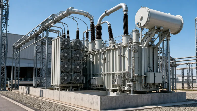
Key takeaways
- A power plant transformer steps up medium-voltage generator output (typically 11 kV to 24 kV) to transmission voltages between 110 kV and 500 kV.
- Generator step-up units require continuous duty margins to handle reactive power extremes across generator capability curves per IEEE C57.116.
- Differential protection (87T) and restricted earth fault protection (64R) provide high-speed sub-cycle fault clearance within the generator-transformer zone.
- Cooling class ratings must accommodate full generator rating with one cooling stage disabled (N-1 cooling) to prevent thermal derating.
- Short-circuit withstand designs must adhere to IEC 60076-5 to resist repeated generator close-in faults without mechanical core-coil displacement.
Quick answer: A power plant transformer (often termed a generator step-up or GSU unit) is a high-capacity power transformer engineered to step up the generator's medium-voltage output—typically 11 kV to 24 kV—to transmission voltage levels between 110 kV and 765 kV for long-distance power grid export.
In thermal, hydroelectric, nuclear, combined-cycle, and large-scale renewable generating stations, the power station transformer represents the primary electrical link between generation assets and the regional transmission network. Operating continuously at base load, these units experience extreme thermal, dielectric, and mechanical stresses distinct from typical distribution assets. Correct sizing, robust fault protection, and vigilant thermal management are essential to prevent unscheduled outages that can cost plant operators tens of thousands of pounds per hour in lost dispatch.
Functional Roles of a Power Station Transformer
A power station transformer fleet in a typical generation facility consists of three primary functional classes: generator step-up units, unit auxiliary transformers, and reserve station service transformers. Each category serves a dedicated operational purpose across the plant electrical topology.
The generator step-up (GSU) unit directly connects to the generator terminal busbars via isolated-phase bus ducting. Operating under continuous full-load conditions, the GSU steps up the generator stator voltage to match the high-voltage transmission substation. Concurrently, the unit auxiliary transformer (UAT) taps off the generator bus to step down generation voltages to medium voltage (such as 6.6 kV or 11 kV), powering critical auxiliary systems such as boiler feedwater pumps, forced-draft fans, and cooling towers.
During plant startup or emergency trips when the primary generator is offline, the station service transformer (SST) draws back-feed energy directly from the transmission network to sustain house loads. Integrating an efficient power transformer within this network requires precise tap-changer coordination and impedance profiling to balance voltage regulation across variable grid conditions. For further grid interconnection topologies, consult our guide on transmission transformer engineering.
Power Plant Transformer Sizing Calculation
Sizing a power plant transformer requires calculating the maximum gross electrical output of the generator while factoring in power factor range, ambient temperature derating, and auxiliary load extraction. Sizing a GSU solely on active power (MW) leads to severe thermal overloading when the generator operates in an over-excited (lagging) state to provide reactive support.
Consider a 300 MW rated turbine-generator designed with a rated lagging power factor of 0.85 and a leading power factor limit of 0.95. The generator terminal voltage is 18 kV, stepping up to a 230 kV grid. The station auxiliary systems take 18 MVA through a dedicated unit auxiliary transformer tapped ahead of the GSU low-voltage terminals.
- Calculate generator gross apparent power ($S_{gen}$):
$$S_{gen} = \frac{P_{rated}}{\cos \phi} = \frac{300\text{ MW}}{0.85} = 352.94\text{ MVA}$$ - Deduct auxiliary load tapped prior to the GSU ($S_{aux}$):
Auxiliary active power at 0.85 pf: $$P_{aux} = 18\text{ MVA} \times 0.85 = 15.3\text{ MW}$$
Net active power through GSU: $$P_{GSU} = 300\text{ MW} - 15.3\text{ MW} = 284.7\text{ MW}$$
Net MVA demand through GSU: $$S_{GSU} = \frac{284.7\text{ MW}}{0.85} = 334.94\text{ MVA}$$ - Apply a continuous margin for grid voltage excursions and ambient extremes:
Per IEEE C57.116 clause 5.2, apply a 10% operating margin to absorb prolonged low-voltage grid conditions requiring full lagging MVAR output without exceeding temperature limits:$$S_{spec} = 334.94\text{ MVA} \times 1.10 = 368.43\text{ MVA}$$
Consequently, the engineering specification calls for a nominal three-phase rating of 370 MVA (ONAF) or 400 MVA (ODAF) to ensure adequate thermal overhead during peak summer ambient temperatures.
Technical Comparison: Power Plant Transformer vs Transmission Power TF
A power tf deployed at a generation facility operates under distinct mechanical and operational constraints compared to a conventional substation grid transformer. The table below delineates the core engineering parameters separating a generating station unit from a transmission grid unit per IEC 60076 and IEEE C57 standards.
| Engineering Parameter | Power Station Transformer (GSU) | Power Grid Transformer (Network Intertie) |
|---|---|---|
| Primary Operating Duty | Continuous steady base-load (often 90%–100% capacity) | Variable, cyclical loading following regional load curves |
| Low-Voltage Bushing Design | High-current termination (up to 25 kA) via isolated phase bus (IPB) | Cable box or standard porcelain/composite outdoor bushings |
| Voltage Ratio Configuration | Step-up (e.g., 15.75 kV / 400 kV) | Step-down or intertie step (e.g., 400 kV / 132 kV) |
| Vector Group Standard | YNd11 or YNd1 (delta generator side, wye grid side) | YNyn0, YNautod11, or YNd11 |
| Tap Changer Configuration | Often de-energised tap changer (DETC); OLTC optional | On-load tap changer (OLTC) on HV or common winding |
| Through-Fault Stress Exposure | High mechanical forces from close-in generator terminal faults | System-wide fault currents damped by line impedances |
| Cooling Arrangement | ODAF / OFAF / OFWF with dual redundant 100% pumping loops | ONAN / ONAF / ODAF with staged radiator fan banks |
Because generator step-up transformers experience massive direct currents during asymmetrical short circuits, their core and winding clamping structures require higher mechanical bracing to satisfy IEC 60076-5 short-circuit withstand criteria.
Critical Protection Schemes for a Power Grid Transformer Interface
A comprehensive protection scheme for a power grid transformer operating in a generating facility must defend against internal phase faults, core saturation, winding ground faults, and thermal runaways. High asset replacement costs dictate multi-layered, redundant protection philosophies.
Biased differential protection (ANSI 87T) functions as the primary high-speed protective boundary, comparing current vector sums across the generator terminals and the transmission switchyard. Because power plant transformers frequently operate under variable excitation, 87T relays require second-harmonic restraint (typically set to 15% threshold) to prevent nuisance tripping during core energisation inrush, alongside fifth-harmonic blocking to prevent false trips during overexcitation conditions defined in IEC 60255-151. For deeper analysis of protective relay logic, review our guide on transformer protection systems.
Restricted earth fault (ANSI 64R) provides sensitive zero-sequence protection covering winding ground faults near the neutral point where standard differential sensitivity drops off. Backing up electrical relays are mechanical monitors, including dual-float Buchholz relays for gas collection and surge detection, pressure relief devices (PRD) with rapid microswitches, and fiber-optic winding temperature probes. Fire deluge systems, detailed in our transformer fire protection design guide, safeguard the physical station structure from oil pool fires in the event of catastrophic bushing failure.
Cooling and Thermal Management in Generation Facilities
Thermal management in a power plant transformer governs asset life expectancy, as sustained operation above rated insulation limits degrades cellulosic paper insulation exponentially per the Arrhenius rate equation. IEEE C57.91 states that winding hot-spot temperatures operating continuously above 110 °C (for 65 °C rise paper) halve insulation structural life every 6 °C to 8 °C increment.
Generating stations employ forced-circulation cooling designs, predominantly ODAF (oil directed, air forced) or OFWF (oil forced, water forced) in hydroelectric installations. Directed oil circulation forces cooled dielectric oil directly through internal winding oil ducts rather than allowing non-uniform buoyancy flow. Cooling pumps and fans should incorporate N-1 redundancy, meaning if one radiator bank or pump fails, the remaining cooling apparatus maintains 100% continuous rated power without exceeding the 65 °C winding average temperature rise limit specified in IEC 60076-2.
Factory Testing and Acceptance Checklist
Rigorous factory acceptance testing (FAT) validates that a power station transformer matches numerical simulations and can withstand decades of electrical transients before leaving the factory floor. Every high-voltage unit must undergo comprehensive routine, type, and special tests according to IEEE C57.12.90 and IEC 60076-1.
- Winding resistance measurements: Verify copper/aluminium cross-sections and connection integrity across all tap positions.
- Voltage ratio and vector group verification: Ensure angular displacement adheres strictly to specified clock notation (e.g., YNd11).
- Short-circuit impedance and load loss: Measure %Z to confirm fault current limitation values fall within ±7.5% of nominal project limits per IEC 60076-1 Table 1.
- Dielectric withstand tests: Apply separate source AC overvoltage, short-duration induced overvoltage with partial discharge monitoring (< 100 pC at 1.5 Um / $\sqrt{3}$), and full lightning impulse tests (BIL) per IEC 60076-3.
- Temperature rise test: Perform heat run testing to determine steady-state oil and hot-spot winding temperature rises under full-load losses.
- Frequency response analysis (FRA): Establish a factory baseline for winding mechanical geometry to detect transport-induced core-and-coil shifts upon site arrival.
For field procedures post-delivery, examine our engineering manual on power transformer factory and acceptance testing.
Next Steps: Specifying and Sourcing
Preparing a procurement specification for a power plant transformer requires providing comprehensive site boundary data: rated MVA capacity, nominal generator and grid voltages, BIL insulation levels, required %Z impedance, cooling class, tap-changer operational requirements, and seismic parameters. For station auxiliary and primary substation tie-ins, explore our range of power transformers, oil-immersed transformers, and integrated transformer substations. To discuss engineering specifications, dielectric oil selection, or project pricing with our technical team, submit your RFQ package via our transformer quotation page or reach out through our engineering contact portal.
Frequently asked questions
What is the difference between a GSU and a power plant transformer?
A generator step-up (GSU) transformer is a specific type of power plant transformer that elevates medium-voltage generator output directly to transmission grid levels. Power plant transformer is a broader category that also encompasses unit auxiliary transformers and station service transformers.
Why do generator step-up transformers use a delta-wye vector group?
GSUs use a delta-wye (YNd) vector configuration to isolate zero-sequence harmonic currents generated by the turbine-generator within the delta winding. The grounded wye connection on the high-voltage side provides an effective neutral point for the transmission grid.
What impedance is typical for a power plant transformer?
Short-circuit impedance for large GSUs typically ranges from 12% to 18% on their self-cooled rating base. This value is engineered to limit downstream switchyard short-circuit currents while maintaining acceptable transient stability margins during grid disturbances.
How long does a power station transformer typically last?
A high-capacity power station transformer exhibits an operational service life of 30 to 40 years when maintained within IEEE C57.91 thermal boundaries. Life duration depends primarily on operating temperatures, oil moisture content, and cumulative short-circuit stresses.
What cooling class is most common for large power plant transformers?
ODAF (Oil Directed, Air Forced) and OFAF (Oil Forced, Air Forced) are the primary cooling methods for large thermal and gas turbine installations. These forced systems circulate oil actively across winding surfaces to dissipate heavy, continuous base-load thermal losses.
Tags: power plant transformer power station transformer power grid transformer power tf


